Trigger counter for measurement device with count values stored in flash memory

a technology of flash memory and trigger counter, which is applied in the field of precision metrology, can solve the problems of limited capacity to track and store operating parameters or information, internal signal processing and memory functions, and inability to provide configurations that achieve similar high accuracy measurements (e.g., micron or submicron level repeatability), and achieves simple interaction and ease of use. , the effect of high reliability data recording and retention

Active Publication Date: 2018-06-07
MITUTOYO CORP
View PDF1 Cites 9 Cited by
  • Summary
  • Abstract
  • Description
  • Claims
  • Application Information

AI Technical Summary

Benefits of technology

[0007]In contrast to the prior art, disclosed herein is a configuration for a touch probe that includes a unique combination of features which allows permanently storing in the touch probe an ongoing accumulated and essentially unlimited count of all touch “trigger” signals generated by the touch probe (e.g., hundreds of millions of “touches”), without the need for an associated size increase, and without a battery, and while allowing high reliability data recording and retention and simple interaction and ease of use in

Problems solved by technology

The performance levels and miniaturization currently demanded in touch probe bodies has typically forced tradeoffs between all elements combined in such devices, particularly when adding a new feature or capability.
Various solutions for data storage in a probe have either used volatile memory (compromising the related reliability and/or ease of use), or required additional components and/or space (e.g., an increased probe size) and/or required a battery (compromising cost, size, and maintenance cost), and/or have otherwise ha

Method used


Image

  • Trigger counter for measurement device with count values stored in flash memory
  • Trigger counter for measurement device with count values stored in flash memory
  • Trigger counter for measurement device with count values stored in flash memory

Examples


Embodiment Construction

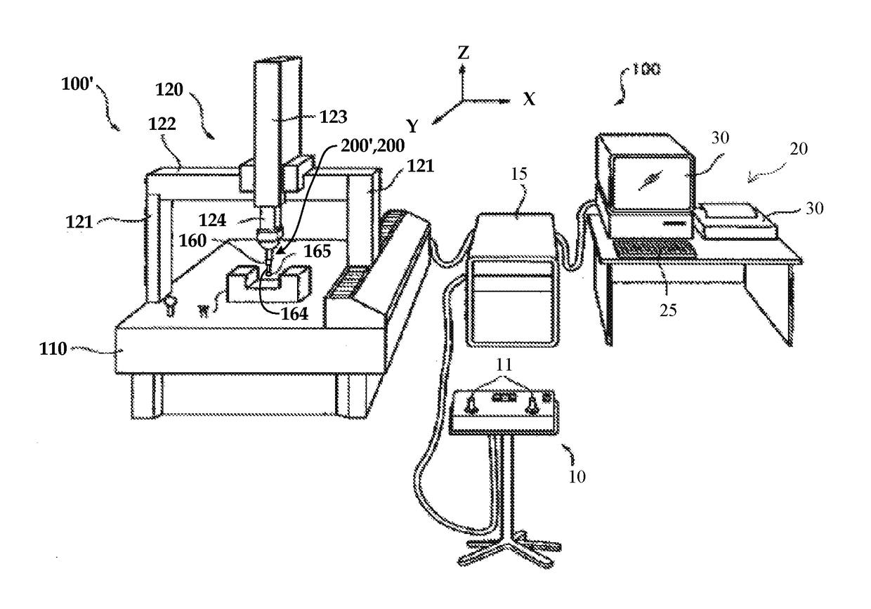
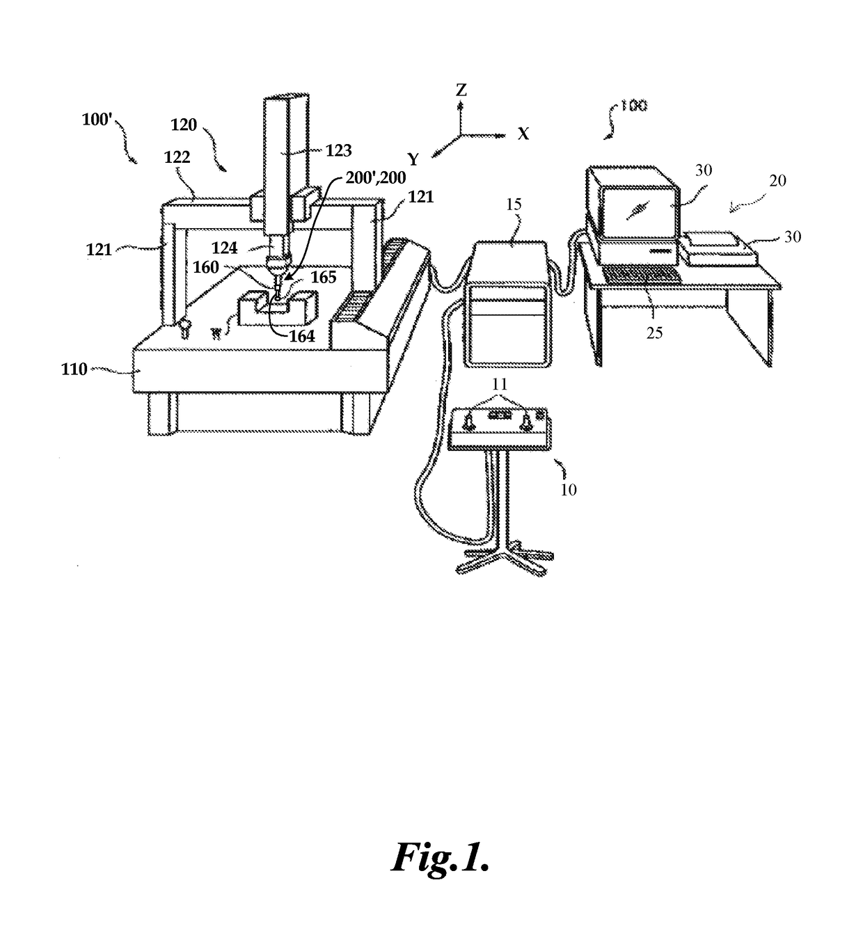
[0016]FIG. 1 is a diagram showing various components of a measuring system 100 including a CMM 100′ utilizing a touch probe 200′ such as that disclosed herein. Coordinate measuring machines (CMMs) are known in the art, for example, in U.S. Pat. Appl. Publ. No. 2011 / 0192044, to Usui, which is hereby incorporated by reference in its entirety. An arrangement of a CMM is illustrated schematically in FIG. 1, showing a measuring system 100 including a CMM 100′, which uses a touch probe 200′. The touch probe 200′ may include a probe body 200. The measuring system 100 includes an operating unit 10, a motion controller 15 that controls movements of the CMM 100′, a host computer 20 and the CMM 100′. The operating unit 10 is coupled to the motion controller 15 and may include joysticks 11 for manually operating the CMM 100′. The host computer 20 is coupled to the motion controller 15 and operates the CMM 100′ and processes measurement data for a workpiece W according to known methods. The host...


PUM


Abstract

A system and method are provided for operating a touch probe for a coordinate measuring machine, wherein a value is permanently stored in the touch probe corresponding to an accumulated number of trigger signals generated in the touch probe over its operating history. For a non-erase cycle during which an erasable trigger counter block (e.g., included in a flash memory) of the touch probe is not erased, increasing values of an accumulated trigger count are stored in N address locations of the erasable trigger counter block. After all of the N address locations have been used, an erase operation sequence is performed, and a new non-erase cycle is initiated for repeating the process. In various implementations, the touch probe may not include an embedded processor or battery, for which the types of circuitry and methods that may be utilized for maintaining and storing the accumulated trigger count are correspondingly limited.

Description

BACKGROUNDTechnical Field[0001]This disclosure relates to precision metrology, and more particularly to touch probes used in coordinate measurement systems.Description of the Related Art[0002]Certain coordinate measurement systems, e.g., one-dimensional or three-dimensional measurement systems, such as coordinate measuring machines (CMMs), may obtain measurements of a workpiece using a touch probe configured to detect when a stylus of the touch probe contacts a workpiece. Touch probes use various types of displacement sensors to sense deflection of the touch probe stylus for an indication that it has contacted a workpiece.[0003]An exemplary prior art CMM utilizing a touch probe is described in U.S. Pat. No. 5,526,576 (the '576 patent), which is hereby incorporated herein by reference in its entirety. The '576 patent discloses a movement mechanism comprising multiple drives for moving the touch probe, and an associated electronic system including features related to processing signal...

Claims


Application Information

Patent Timeline
IPC IPC(8): G01B5/012
CPCG01B5/012G01B7/016G01B21/047
Inventor JANSSON, BJORN ERIK BERTIL
Owner MITUTOYO CORP
Why Eureka
Try Eureka