Optical system with compact collimating image projector

Inactive Publication Date: 2018-06-07
LUMUS LTD
View PDF7 Cites 38 Cited by
  • Summary
  • Abstract
  • Description
  • Claims
  • Application Information

AI Technical Summary

Benefits of technology

[0006]The present invention is an optical system with a compact collimating image projector. Certain preferred embodiments of the present invention provide a simple and compact solution for

Problems solved by technology

As the desired field-of-view (FOV) of the system increases, conventional optical modules of this type become heavier and bulkier, and hence impractical, even for a moderate performance device.
This is a major drawback for all kinds of displays, but especially in head mounted applications, where the system must necessarily be as light and compact as possible.
The quest for compactness has led to several different complex optical solutions, many of which are still not sufficiently compact for mo

Method used


Image

  • Optical system with compact collimating image projector
  • Optical system with compact collimating image projector
  • Optical system with compact collimating image projector

Examples


Example

[0031]The present invention is an optical system with a compact collimating projector coupled to a light-guiding substrate.

[0032]The principles and operation of optical systems according to the present invention may be better understood with reference to the drawings and the accompanying description.

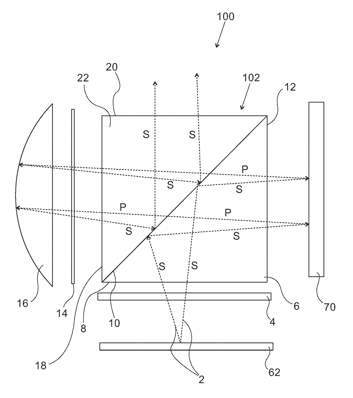
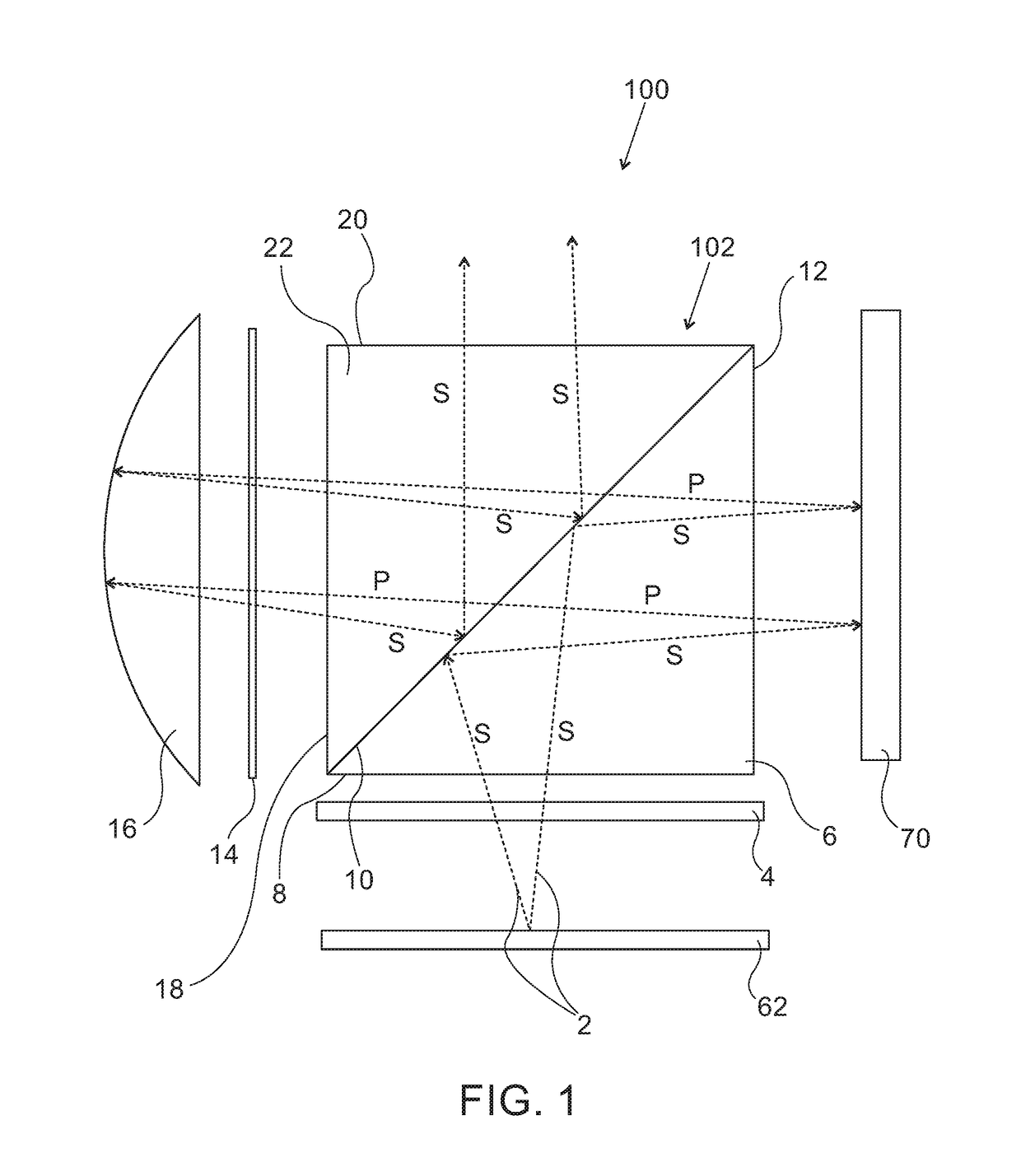
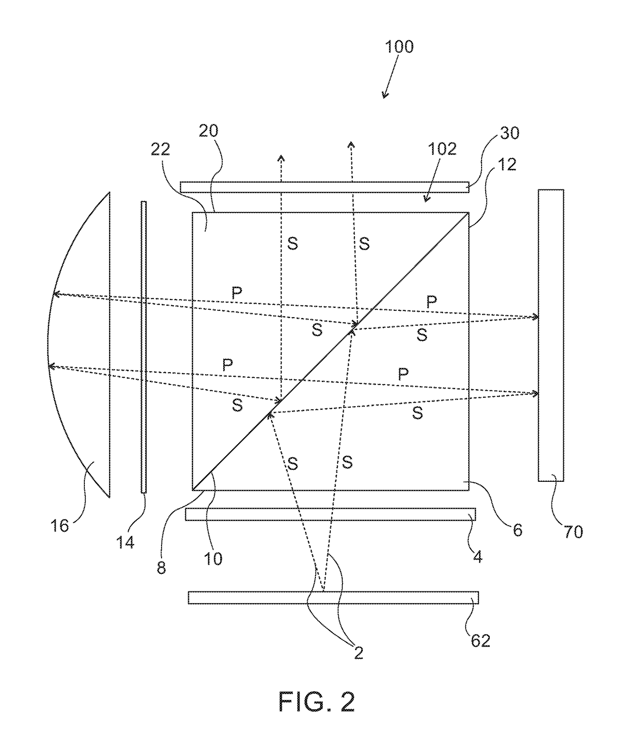
[0033]Referring now to the drawings, FIGS. 1, 2, 4 and 7-8 illustrate various implementations of an optical system, generally designated 100, constructed and operative according to various aspects of the present invention. In general terms, system 100 includes an image-collimating prism 102, formed from a light-wave transmitting material, which has a number of external surfaces including a light-wave entrance surface 8, a light-wave exit surface 20, an image display surface 12 and a collimation surface 18. A polarization-selective beam splitter configuration 10 (which may be referred to in short as “PBS 10”) is deployed within prism 102 on a plane oblique to light-wave entrance surface 8...


PUM


Abstract

An optical system (100) includes an image-collimating prism (102) having external surfaces which are associated with: a polarized source; reflective-display device (70); at least one light-wave collimating component (16) and a light-wave exit surface (20), respectively. A polarization-selective beam splitter configuration (10) is deployed within the prism (102) on a plane oblique to the light-wave entrance surface (8). The reflective-display device is illuminated by light reflected from the beam splitter configuration (10), and generates rotation of the polarization corresponding to bright regions of the image. An image from the reflective-display device (70) is selectively transmitted by the polarization-selective beam splitter configuration (10), is collimated by the collimating component (16), reflected from the polarization-selective beam splitter configuration (10) and is projected through the exit surface (20). In some implementations, an additional polarizer located at or near the exit surface helps to optimize extinction of unwanted illumination rays.

Description

FIELD AND BACKGROUND OF THE INVENTION[0001]The present invention relates to optical systems and, in particular, it concerns an optical system with a compact collimating image projector.[0002]Compact optical devices are particularly needed in the field of head-mounted displays (HMDs), wherein an optical module performs functions of image generation (an “imager”) and collimation of the image to infinity, for delivery to the eye of a viewer. The image can be obtained from a display device, either directly from a spatial light modulator (SLM), such as a cathode ray tube (CRT), a liquid crystal display (LCD), a liquid crystal on silicon (LCoS), a digital micro-mirror device (DMD), an OLED display, a scanning source or similar devices, or indirectly, by means of a relay lens or an optical fiber bundle. The image, made up of an array of pixels, is focused to infinity by a collimating arrangement and transmitted into the eye of the viewer, typically by a reflecting surface or a partially re...

Claims


Application Information

Patent Timeline
IPC IPC(8): G02B27/28G03B21/00G03B21/20G02F1/1362G02B27/30
CPCG02B27/283G03B21/006G03B21/2073G03B21/2006G02F1/136277G02B27/30G02F2203/02G02B5/3025G02B5/3058G02B5/30G02B27/10G02B27/285
Inventor GELBERG, JONATHANGILO, MORDECHAIBAR MEIR, AVIADFROMMER, AVIV
Owner LUMUS LTD
Why Eureka
Try Eureka