
Multi-rotor UAV flight control method and system

a multi-rotor, uav technology, applied in the field of remote control of unmanned aerial vehicles, can solve the problems of increasing risks, reducing working efficiency, and the most difficult part of flying rotary wing drones remotely, so as to improve the efficiency and safety of flying rotary wing drones, increase flight safety, and high level of situational awareness

Active Publication Date: 2018-06-07
SWYFT AERONAUTICAL TECH LTD
View PDF4 Cites 6 Cited by
  • Summary
  • Abstract
  • Description
  • Claims
  • Application Information

AI Technical Summary

Benefits of technology

This patent improves drones by giving the operator better information about what's happening. This makes flying safer and reduces costs. The goal is to make it possible to fly the drone from the operator's perspective, regardless of the direction the drone's body is facing.

Problems solved by technology

The most difficult part of flying rotary wing drones is controlling them remotely.
This difficulty arises from decrease of the situational awareness of the operator, which in turn, significantly decreases working efficiency and at the same time increases risks.
Low working efficiency results in high operating costs, and risks present even higher costs associated with collision inflicted hardware damages and human injuries.
Decreasing any of the two dramatically reduces the situational awareness of the operator and hence his ability to control the rotary wing drone and to accomplish the mission's purpose.
Attempting to simultaneously perform those two distinct operations, which are taking place in different reference systems with different rate of change, severely harm the operator's attention / concentration levels.
Moreover, remotely flying a rotary wing drone, where the operator is not onboard, intrinsically deprives the operator of sensations of speed, acceleration, noise, distance, three-dimensional image of space, directions (right / left), direction of propagation (forward / backward, to / from) and inclination (pitch / roll).
Additionally, the distance between the operator and the rotary wing drone, optically converge all objects in the distance such that the operator can't distinguish the rotary wing drone from objects surrounding it.
All these dramatically degrade the situational awareness of the operator and thus his ability to perform the mission efficiently and safely.
In contrary, because rotary wing drone can change the direction of its flight and its speed abruptly, the ability to predict the location and direction of propagation of the rotary wing drone is severely tampered, and hence also the operator's situational awareness.

Method used


Image

  • Multi-rotor UAV flight control method and system
  • Multi-rotor UAV flight control method and system
  • Multi-rotor UAV flight control method and system

Examples


Embodiment Construction

[0019]The invention will be described more fully hereinafter, with reference to the accompanying drawings, in which certain possible embodiments of the invention are shown. The invention may, however, be embodied in many different forms and should not be construed as limited to the embodiments set forth herein; rather these embodiments are provided so that the disclosure will be thorough and complete, and will fully convey the scope of the invention to those skilled in the art.

[0020]The description that follows refers to a multi-rotor UAV as an example, albeit, the same solution is applicable to multirotor UAVs, unmanned helicopters and to ducted-fan air vehicles. All these UAV types are referred to as Rotary Wing Drone.

[0021]Throughout the rest of the specifications and the claims we shall use the following terms as they are defined hereunder.

[0022]Natural plane is a plane that passes through the drone's center of gravity and is perpendicular to the yaw axis of the rotary wing dron...


PUM


Abstract

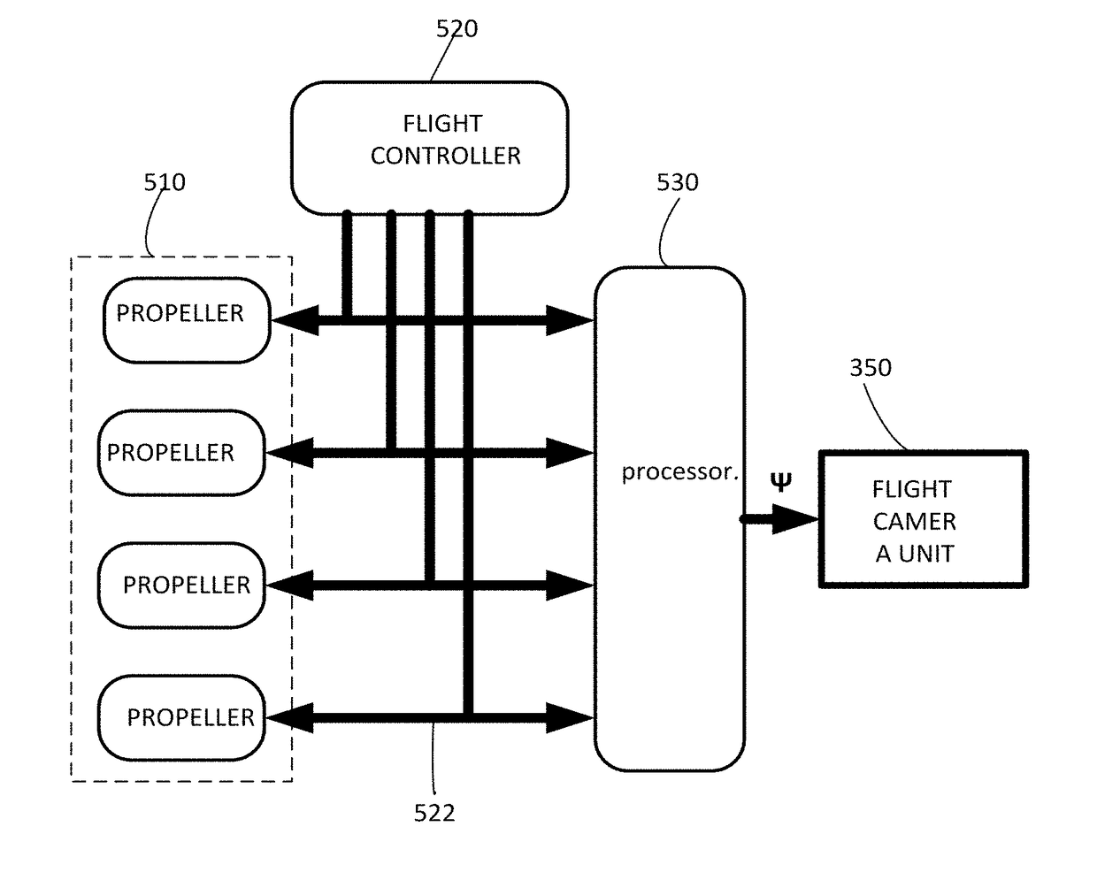
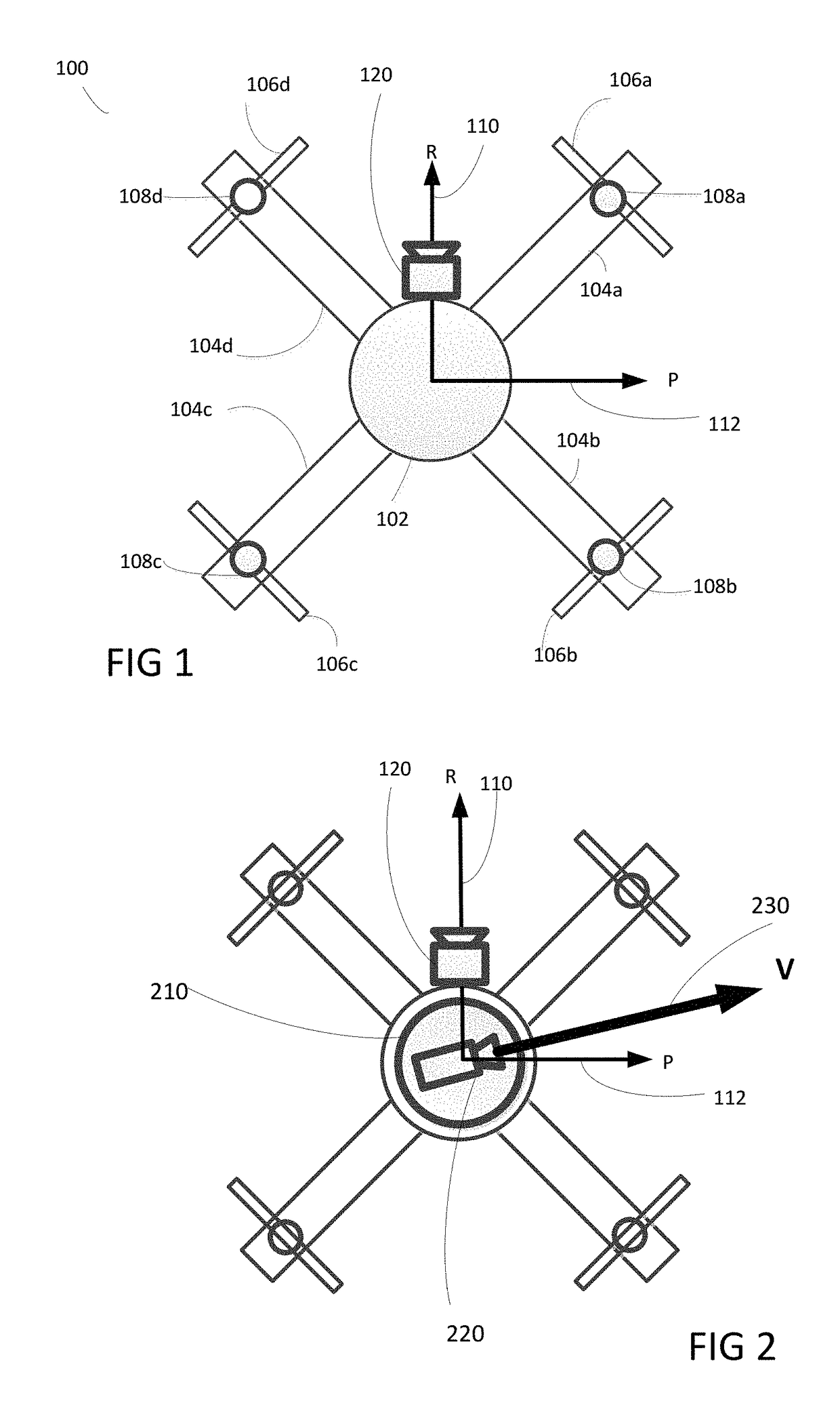
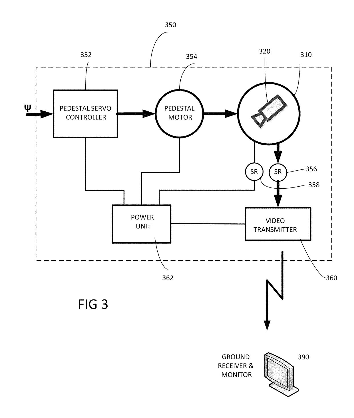
Disclosed herein is a method and system for flying rotary wing drone. An add-on flight camera that is free to rotate around the vehicle's yaw axis is attached to the drone. The flight camera is automatically looking in the direction of its flight. The video from the flight camera is streamed to the operator's display. Thus the rotary wing drone can fly in any direction with respect to its structure, giving the operator a first person view along the flight path, thus keeping high level of situational awareness to the operator. The information required for controlling the camera orientation is derived from sensors, such as GPS, magnetometers, gyros and accelerometer. As a backup mode the information can be derived from propeller commands or tilt sensors.

Description

CROSS REFERENCE TO RELATED APPLICATION[0001]This application claims the benefit of U.S. Provisional Patent Application 62 / 197,569 filed on 28 Jul. 2015, which is incorporated herein by reference.TECHNICAL FIELD[0002]The present invention generally relates to the field of remotely controlling Unmanned Aerial Vehicle (UAV), and more particularly, controlling remotely the flight of multi-rotor UAV or ducted-fan UAV.BACKGROUND ART[0003]Multi-rotor UAV (and multirotor copters in general) configurations have become popular in UAV (Unmanned Aerial Vehicle) as payload carrying platforms. They are known for their simplicity and for their high maneuverability. They are used for military as well as for civilian purposes. Such multi-rotor UAVs are sometimes also referred to as tri-copter, quadcopter, hexa-copter and octocopter, quads and drones. From now on we refer to these UAV's as Rotary Wing Drones.[0004]The most difficult part of flying rotary wing drones is controlling them remotely. This...

Claims


Application Information

Patent Timeline
Patent Type & Authority Applications(United States)
IPC IPC(8): G05D1/00B64C39/02G01C21/16G01R33/02H04N7/18H04N5/232H04N5/33
CPCG05D1/0038B64C39/024G01C21/165G01R33/02H04N7/185H04N5/23238H04N5/33B64C2201/024B64C2201/127B64C2201/146B64U2101/30B64U10/14G05D2109/254G05D1/2247G05D1/689G05D2105/80H04N23/698B64U2201/20B64U2201/104
Inventor MARGOLIN, JOSHUABEN-ANAT, ROY
Owner SWYFT AERONAUTICAL TECH LTD
Learn More