Fast method for identifying coil misalignment/mutualcoupling in wireless charging systems

a wireless charging and mutual coupling technology, applied in the direction of transmission, electrical equipment, batteries circuit arrangements, etc., can solve the problems of increasing the cost and overall complexity of the system, difficulty in identifying coil misalignment, and limited alignment, so as to reduce the mutual inductance between coils and achieve the effect of rapid calculation of coil misalignmen

Active Publication Date: 2018-06-07
THE UNIVERSITY OF HONG KONG
View PDF4 Cites 25 Cited by
  • Summary
  • Abstract
  • Description
  • Claims
  • Application Information

AI Technical Summary

Benefits of technology

[0007]The present invention relates to a method and apparatus to calculate coil misalignment in wireless charging, in which the time taken to calculate the necessary system parameters (i.e. mutual inductance between coils) is greatly reduced, e.g., to less than a minute and, more particularly, relates to rapid calculation for coil misalignment in wireless charging of electric vehicles.
[0008]The proposed method can be implemented in the same circuit structure as shown in FIG. 1; but, the use of intelligent or evolutionary algorithms in the first process of system parameter identification can be eliminated. Unlike the use of evolutionary algorithms, which typically require tens of minutes to determine the system parameters, this proposed method can determine the mutual inductance terms within a very short time (in terms of seconds rather than tens of minutes).
[0010]For parking (EV charging application), since only the mutual inductance will be changed, the proposed new method can generate sufficient number of equations to solve the unknown system parameters very quickly (in seconds).

Problems solved by technology

Since it is not easy to park the vehicle in the exact location each time, the misalignment between the transmitter and receiver coils has become a challenging issue.
Some cases alignment is also limited by the parking position.
However, the additional wireless communication module increases the cost and the overall complexity of the system.
In this previous patent application, the first process usually takes a fairly long time (in terms of tens of minutes if a fast processor is used) to determine the system parameters including the mutual inductance terms among the coupled windings.

Method used


Image

  • Fast method for identifying coil misalignment/mutualcoupling in wireless charging systems
  • Fast method for identifying coil misalignment/mutualcoupling in wireless charging systems
  • Fast method for identifying coil misalignment/mutualcoupling in wireless charging systems

Examples


Embodiment Construction

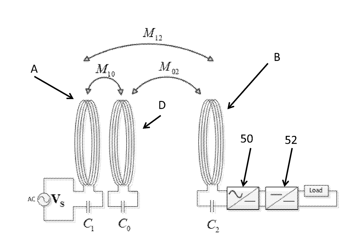
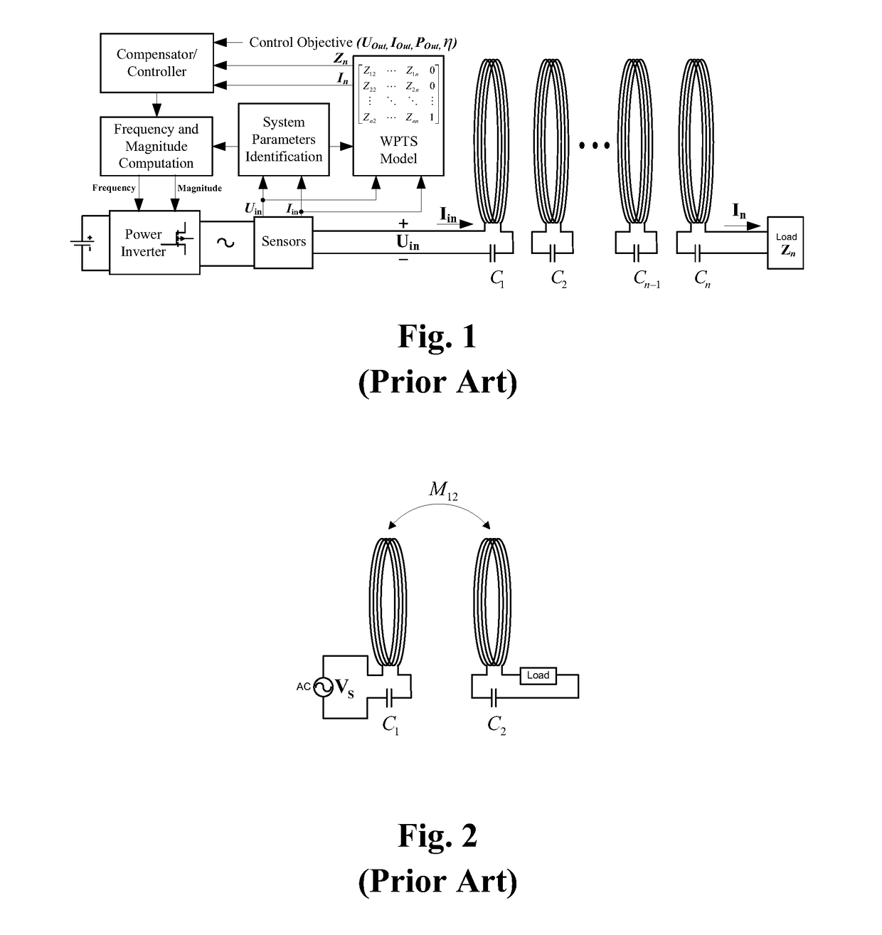
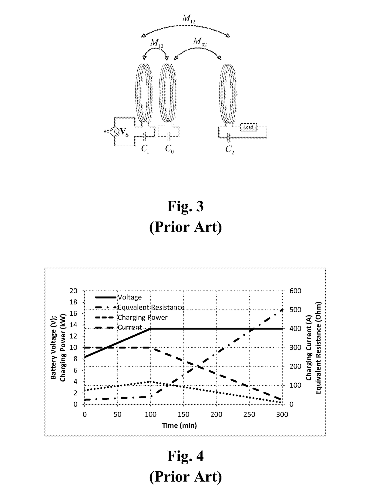
[0028]The proposed method of the present invention may be explained with the use of a 2-coil wireless power transfer system as shown in FIG. 2 and a 3-coil system which has a relay resonator between the transmitter coil and the receiver coil as shown in FIG. 3. The advantage of using a 3-coil system can be found in reference: W. X. Zhong et al., “A Methodology for Making a Three-Coil Wireless Power Transfer System More Energy Efficient Than a Two-Coil Counterpart for Extended Transfer Distance”, IEEE Transactions on Power Electronics, vol. 30, pp. 933-942, 2015 (the “Zhong 2015 article 1”).

[0029]The descriptions given below are based on wireless charging of electric vehicles (EV). However, it should be noted that the proposed method is also applicable to other wireless charging systems.

[0030]There are numerous publications on wireless charging of electric vehicles. Examples are: J. G. Hayes et al., “Wide-load-range resonant converter supplying the SAE J-1773 electric vehicle inducti...


PUM


Abstract

Methods and apparatus for determining the misalignment and mutual coupling between the transmitter coil and receiver coil, with or without an intermediate relay resonator coil, of a wireless power charging system are provided. The determination can be made without using any direct measurement from the receiver circuit. The technic involves exciting the transmitter coil of the wireless power charging system at several frequencies with equal or different input voltage / current, such that the number of equivalent circuit equations is at least equal to the number of unknown terms in the equations. The methods use the knowledge of only the input voltage and the input current of the transmitter coil. This means that the mutual inductance or magnetic coupling coefficient between the transmitter and receiver coils can be determined based on the information obtained from the transmitter circuit and there is no need for any wireless communication from or direct measurements of the receiver circuit.

Description

FIELD OF THE INVENTION[0001]The present invention relates generally to a fast method for identifying coil misalignment and mutual coupling of transmitter and receiver coils in wireless charging systems without using direct measurement from the receiver coil.BACKGROUND OF THE INVENTION[0002]While wireless power was pioneered by Nicola Tesla a century ago, it has gained substantial attention for commercial applications only in the last two decades. One reason for this is the emerging availability of power electronics, which provide a technical means to process electrical power at high speed with high frequency switching, thus acting as an enabling technology for wireless power transfer. Generally, a wireless power transfer system consists of at least a transmitter module (comprising a transmitter circuit and a transmitter coil) and at least one receiver module (comprising a receiver coil and a receiver circuit). Tesla pointed out in his research that using magnetic coupling with reson...

Claims


Application Information

Patent Timeline
Patent Type & Authority Applications(United States)
IPC IPC(8): H02J50/90H04B5/00H02J50/12H02J50/50
CPCH02J50/90H04B5/0031H04B5/0037H02J50/12H02J50/50H02J7/025H04B5/0081
Inventor LIN, DEYANHUI, SHU YUEN, RON
Owner THE UNIVERSITY OF HONG KONG
Why Eureka
Try Eureka