Polishing pad and polishing method

a technology of polishing pad and polishing method, which is applied in the direction of grinding/polishing apparatus, grinding machine, manufacturing tools, etc., can solve the problems of increasing the cost of the polishing process, increasing the complexity of assembly, and changing the temperature so as to reduce the temperature gradient of the polishing pad and achieve excellent applicability

Active Publication Date: 2018-06-14
IV TECH CO LTD
View PDF0 Cites 1 Cited by
  • Summary
  • Abstract
  • Description
  • Claims
  • Application Information

AI Technical Summary

Benefits of technology

[0006]The invention provides a polishing pad and a polishing method that reduce a temperature gradient of the polishing pa

Problems solved by technology

However, the heat generated by friction during the polishing process changes the temperature of the polishing pad.
However, when working with other equipment, not only the cost of the polishing process is increased, but the assembly is also more complicated.
However,

Method used


Image

  • Polishing pad and polishing method
  • Polishing pad and polishing method
  • Polishing pad and polishing method

Examples


Embodiment Construction

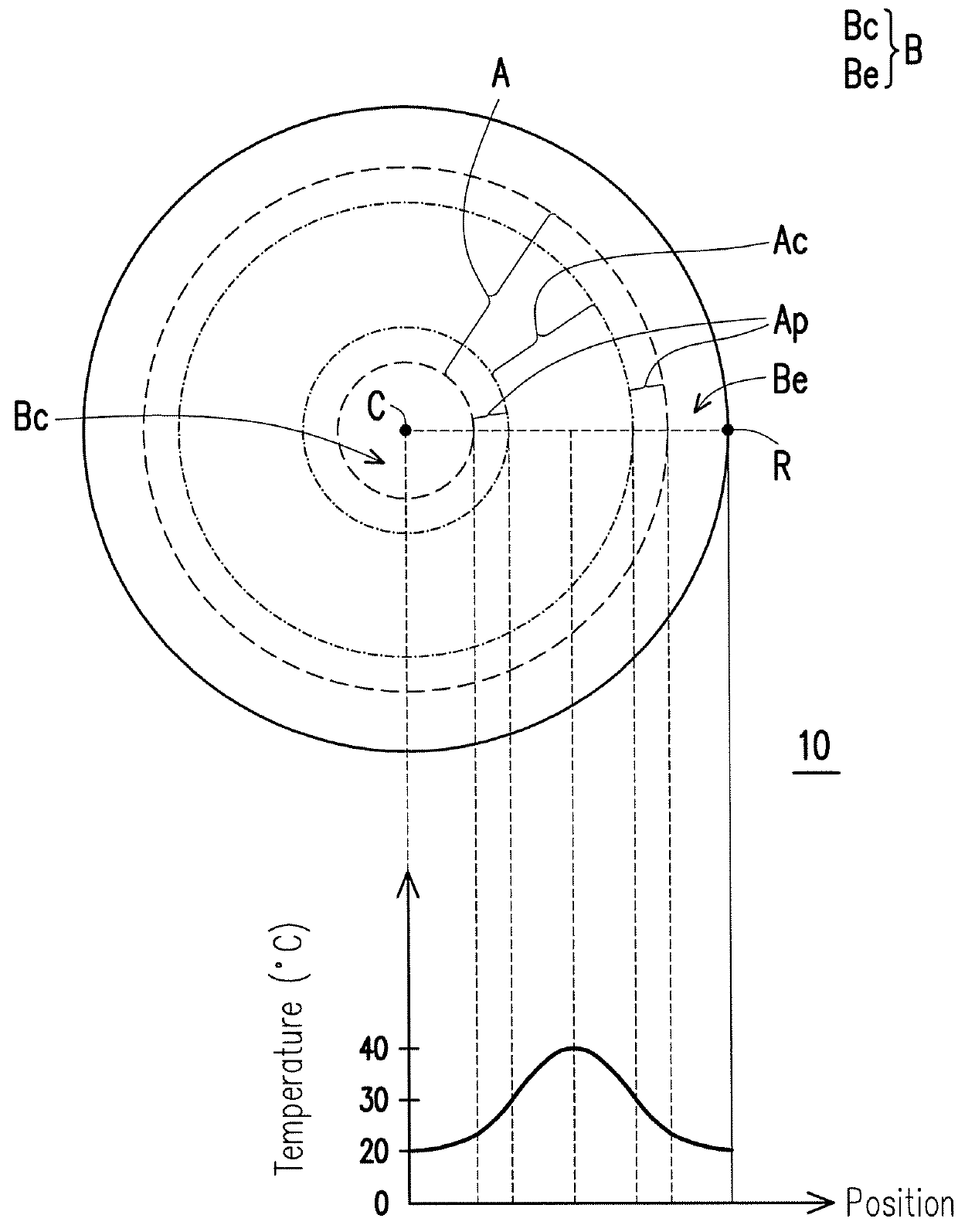
[0020]FIG. 1 illustrates a top schematic diagram of a polishing pad according to an embodiment of the invention. Referring to FIG. 1, a polishing pad 10 includes a polishing track region A and a non-polishing track region B. The polishing track region A includes a central region Ac and a peripheral region Ap surrounding the central region Ac. The non-polishing track region B includes a center region Bc and an edge region Be, wherein the center region Bc is located on an inner side of the polishing track region A, and the edge region Be is located on an outer side of the polishing track region A. It is noted that when the polishing pad 10 is used to perform a polishing procedure on an object, the object is substantially placed in the polishing track region A. When the polishing procedure is performed, relative motion between the object and the polishing pad 10 causes the polishing track region A to be in an annular distribution, and the relative motion is, for example, clockwise or c...


PUM


Abstract

A polishing pad is provided. The polishing pad, suitable for a polishing procedure using a slurry containing water, includes a polishing track region and a first reactant. The polishing track region includes a central region and a peripheral region surrounding the central region. The first reactant is disposed in the central region of the polishing track region, wherein the first reactant is able to react endothermically with the water in the slurry.

Description

CROSS-REFERENCE TO RELATED APPLICATION[0001]This application claims the priority benefit of Taiwan application serial no. 105140788, filed on Dec. 9, 2016. The entirety of the above-mentioned patent application is hereby incorporated by reference herein and made a part of this specification.BACKGROUND OF THE INVENTIONField of the Invention[0002]The invention relates to a polishing pad and a polishing method, and in particular, a polishing pad of which a temperature distribution is changed during a polishing procedure and a polishing method using the polishing pad.Description of Related Art[0003]In the manufacturing process of industrial devices, the polishing process is currently the more commonly used technique to planarize the surface of an object to be polished. During the polishing process, a slurry is selected to be provided between the object surface and the polishing pad, and planarization is performed through mechanical friction generated by relative motion between the objec...

Claims


Application Information

Patent Timeline
IPC IPC(8): B24D3/34B24B29/02B24B55/02
CPCB24D3/346B24B29/02B24B55/02B24B37/015B24B37/26B24B37/34B24B37/24
Inventor WANG, YU-PIAOCHEN, I-PING
Owner IV TECH CO LTD
Why Eureka
Try Eureka