Hydraulic device comprising a sealing element

a sealing element and hydraulic device technology, applied in mechanical devices, rotary or oscillating piston engines, rotary piston engines, etc., can solve the problems of increasing leakage with each change of direction, affecting the reliability of fittings, and affecting the adjustment of hydraulic pumps, so as to reduce the complexity of fittings, increase the reliability of fittings, and reduce costs.

Active Publication Date: 2018-06-14
SCHWABISCHE HUTTENWERKE AUTOMOTIVE CMBH
View PDF13 Cites 0 Cited by
  • Summary
  • Abstract
  • Description
  • Claims
  • Application Information

AI Technical Summary

Benefits of technology

[0007]An aspect of the invention is an improved hydraulic device, specifically a hydraulic pump or cam shaft phase setter, in terms of sealing off a sealing gap of the type mentioned. The intention is to reduce the fitting complexity, increase the fitting reliability and where possible reduce the costs, in comparison with multi-part sealing devices.

Problems solved by technology

Comparable problems occur in hydraulic pumps which can be adjusted in terms of their delivery volume.
In operational states in which a sufficient hydraulic pressure is not yet available, for example when the pump is being started, this can cause an unintended and in particular undefined leakage across the sealing gap and therefore delayed suctioning by the pump.
If the hydraulic fluid can be applied to the actuating member in each of the two directions in which it can be adjusted, a pressure difference across the sealing gap which changes direction can cause increased leakage with each change of direction.
Using a separate spring element does however increase the costs incurred by the seal.
Aside from the higher manufacturing and fitting costs, a two-part sealing design also proves disadvantageous in comparison with an unmodified sealing element with regard to the error rate during fitting.
A drop-in-pressure test may not detect that a spring element is incorrectly fitted or is missing.
The plurality of parts also increases the likelihood that a spring element which is imperfectly fitted enters the pump or phase setter in the course of operations, causing malfunction or failure.

Method used


Image

  • Hydraulic device comprising a sealing element
  • Hydraulic device comprising a sealing element
  • Hydraulic device comprising a sealing element

Examples


Embodiment Construction

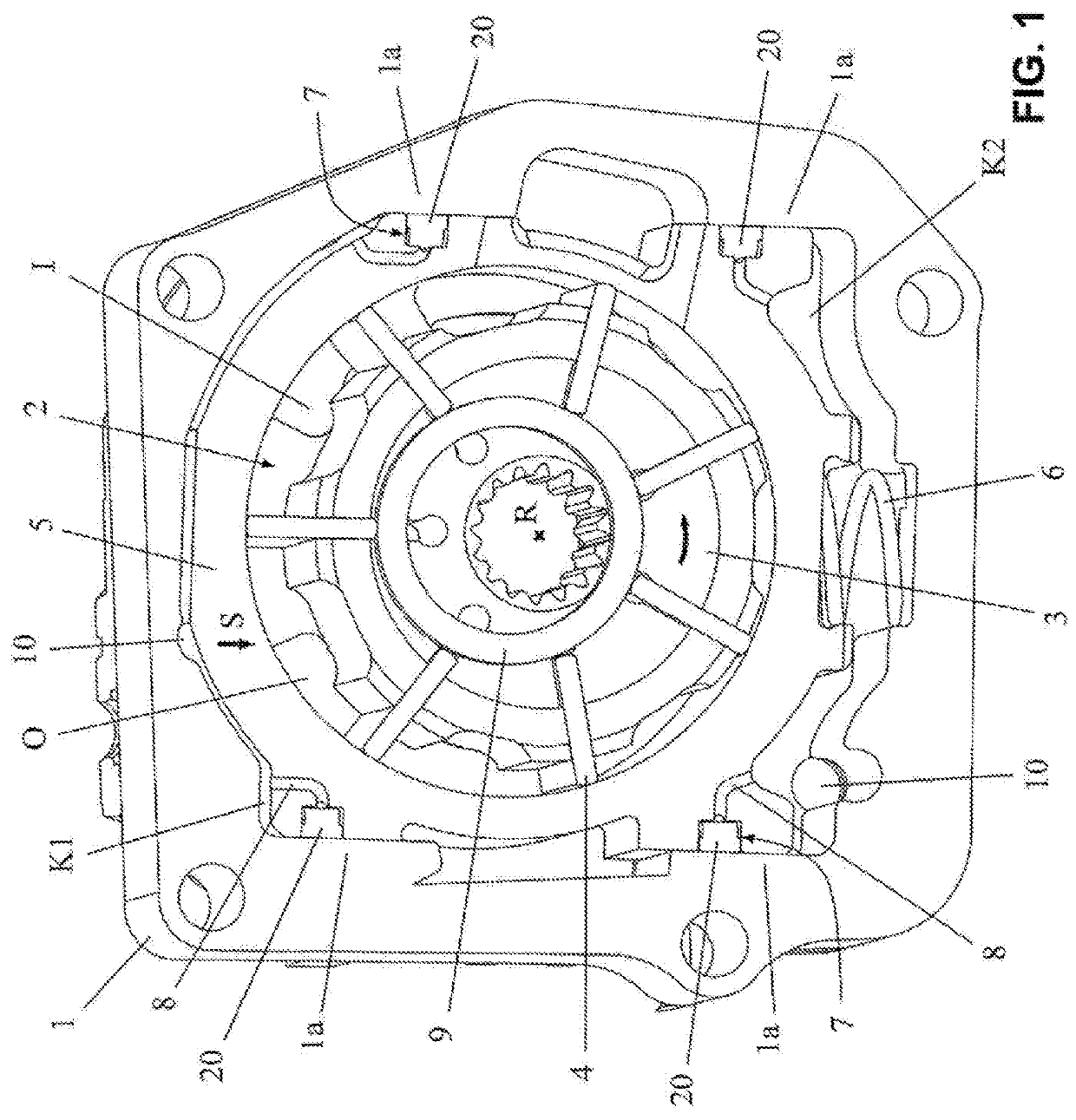
[0130]FIG. 1 shows a hydraulic rotary pump, which is embodied by way of example as a vane cell pump, in a perspective view onto an end-facing side of the pump. The pump comprises a housing 1. A housing cover has been removed, such that the functional components of the pump which are accommodated by the housing 1 can be seen. A delivery chamber 2 is formed in the housing 1, wherein a delivery rotor 3 is arranged in the delivery chamber 2 such that it can be rotated about a rotational axis R. The delivery chamber 2 comprises a low-pressure side and a high-pressure side. When the delivery rotor 3 is rotary-driven in the rotational direction indicated, i.e. anti-clockwise, a hydraulic fluid—for example, a lubricating oil or working oil—flows into the delivery chamber 2 via an inlet channel on the low-pressure side of the pump and through an inlet I and is expelled from the delivery chamber 2 at an increased pressure on the high-pressure side through an outlet O and discharged via an adj...


PUM


Abstract

A hydraulic device for an internal combustion engine or a gearing system, the hydraulic device including a housing featuring a chamber wall structure which delineates a pressure chamber for a pressurised hydraulic fluid; an actuating member which can be adjusted in the housing relative to the chamber wall structure in an actuating direction and in an actuating counter direction opposite to the actuating direction in order to adjust the delivery volume or phase position; and a sealing element including a sealing structure and a spring structure which is supported or moulded on one of the chamber wall structure and the actuating member, preferably the actuating member, and presses the sealing structure into sealing contact with the other of the chamber wall structure and the actuating member with a spring force in order to seal off the pressure chamber. The sealing structure and the spring structure are moulded in one piece.

Description

CROSS REFERENCE TO RELATED APPLICATIONS[0001]This application claims priority to German Patent Application No. 10 2016 124 104.0, filed Dec. 12, 2016, the contents of such application being incorporated by reference herein.FIELD OF THE INVENTION[0002]The invention relates to a hydraulic device for an internal combustion engine or a gearing system. More specifically, the invention is directed to a sealing element of the hydraulic device, which serves to seal off a sealing gap which delineates a pressure chamber of the hydraulic device and is formed between a chamber wall structure and an actuating member which can be moved relative to the chamber wall structure. The hydraulic device is a hydraulic pump exhibiting an adjustable delivery volume, or a hydraulic cam shaft phase setter for adjusting the phase position of a cam shaft relative to a crankshaft of an internal combustion engine. The hydraulic device can be arranged in or on the internal combustion engine or a gearing system or...

Claims


Application Information

Patent Timeline
Patent Type & Authority Applications(United States)
IPC IPC(8): F01C19/12F01C1/344
CPCF01C19/12F01C1/344F01L1/047F01L1/3442F01L2001/34479F04C14/18F04C15/00F04C15/0003F01L2001/34426F01L2001/34433F04C15/0015
Inventor MEINIG, UWEBAUR, DOMINIK
Owner SCHWABISCHE HUTTENWERKE AUTOMOTIVE CMBH
Why Eureka
Try Eureka