Direct analysis sampler with heat sink

a sampler and heat sink technology, applied in the direction of material analysis, instruments, withdrawing sample devices, etc., can solve the problems of preventing rapid solidification of molten metal samples, inability to reliably analyze conventional devices, and loss of potential economic benefits

Active Publication Date: 2018-06-14
HERAEUS ELECTRO NITE INT NV
View PDF0 Cites 6 Cited by
  • Summary
  • Abstract
  • Description
  • Claims
  • Application Information

AI Technical Summary

Benefits of technology

[0019]The invention relates to a rapid chilled sampler which is filled with molten metal in the immersion direction parallel to the longitudinal axis and which produces a metallurgical sample analyzed on an OES without surface preparation. Part of the mold which is responsible for the largest chill mass is inseparable from the sample itself. Accordingly, the sample housing, rather than the sample itself, is configured to provide the greatest utility on existing optical emission spectrographs which, at present, require an analyzable surface to be of certain dimensions.

Problems solved by technology

However, this could only be achieved by a uniform filling of the sample cavity and rapid chilling of the molten metal sample, such that the entire sample section presented for analysis freezes uniformly and without surface oxidation.
Unnecessary constraints imposed upon the shape and size of the metal sample for OES, discussed later, result in the prior art sample volume being over dimensioned from the minimum volume of metal required to arrive at the minimum necessary analyzed surface.
The unnecessary large sample volumes of the prior art devices thus preclude rapid solidification of the molten metal sample.
As such, conventional devices cannot be reliably analyzed by OES without surface preparation and thereby potential economic benefit is lost.

Method used


Image

  • Direct analysis sampler with heat sink
  • Direct analysis sampler with heat sink
  • Direct analysis sampler with heat sink

Examples


example 1

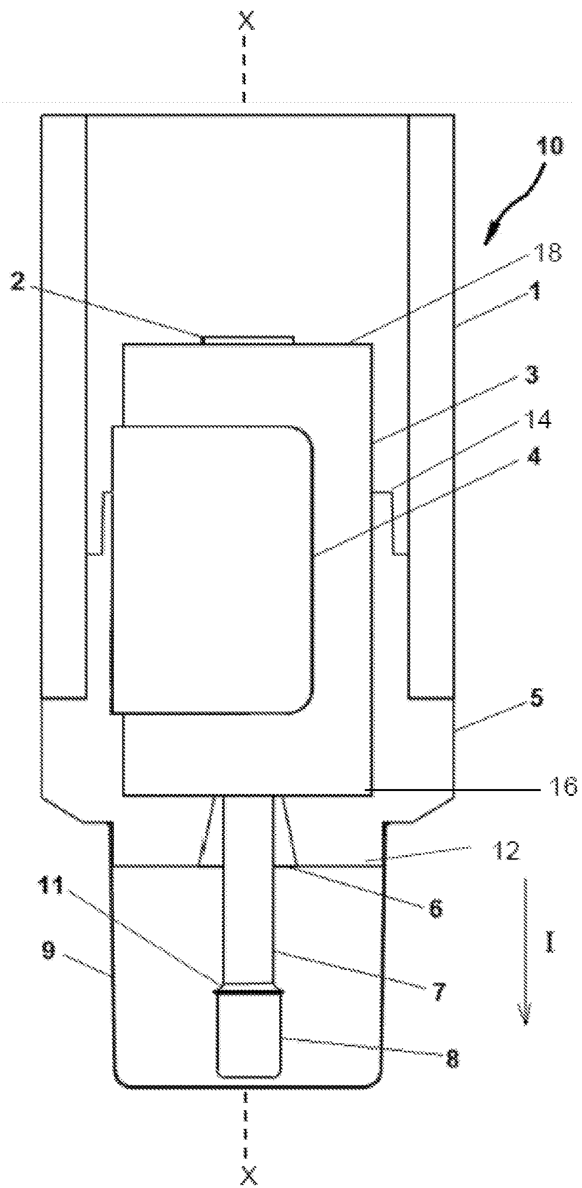
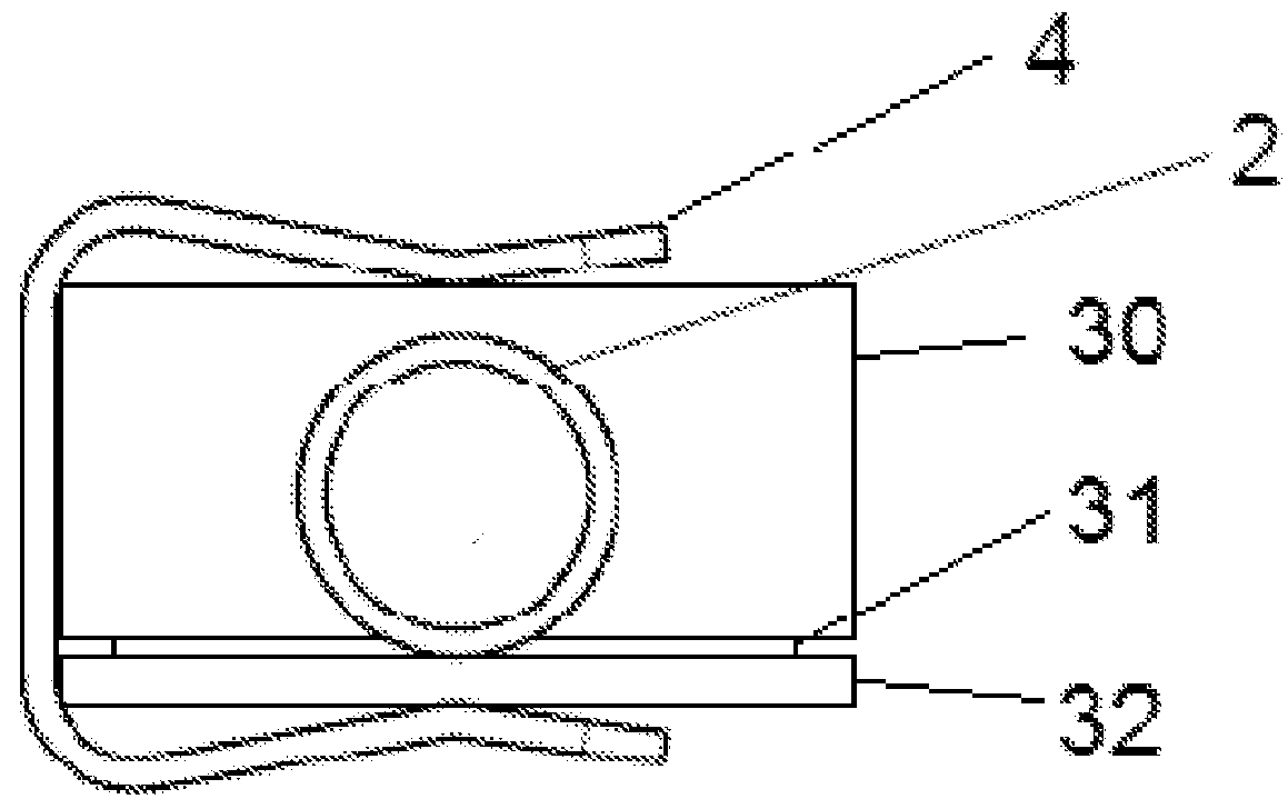
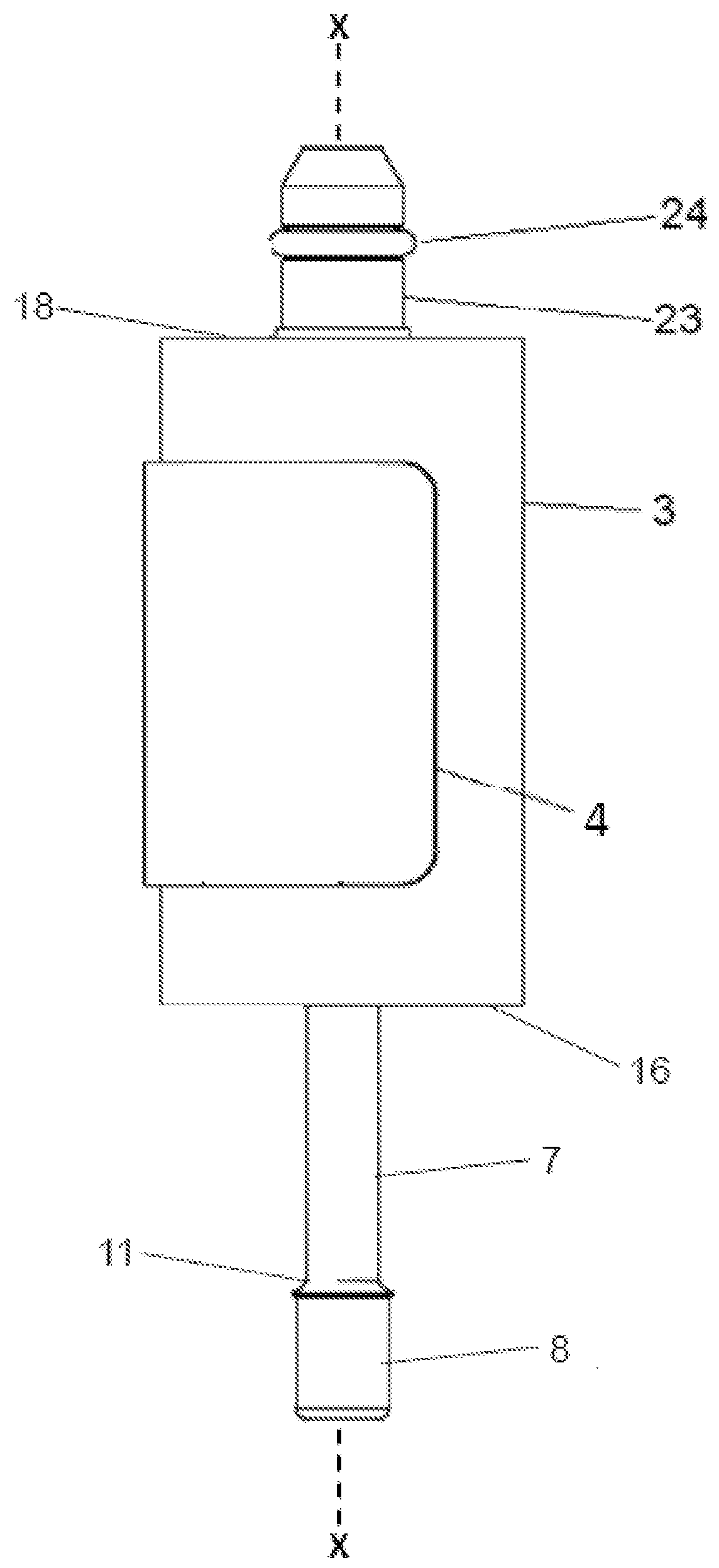
[0112]The probe 10 including the sample chamber 3 shown in FIG. 6 is pneumatically coupled to the probe holder with the simple push-on, pull off connector 23. The connector 23 is either directly attached to the sampling chamber 3 by the coupler 2 or at a distance joined by a pneumatic line. Closing of the gas circuit provides for a slight overpressure of inert purge gas. Using the probe holder for mechanical advantage, the probe 10 is immersed in a molten metal bath and remains at a predetermined distance beneath the metal surface for a specified duration. During this immersion, the protective cap 9 of the measuring head 5 which is designed to withstand destruction while passing through the slag floating upon the metal surface, melts away, thus exposing the smaller protective cap 8 of the inflow conduit 7. As the first protection cap 4 also subsequently melts, the overpressure of inert gas is released and the inert purge gas flows from the probe holder through the gas connector 23 (...

example 2

[0122]A solidified metal sample S suitable for analysis using an OES from a molten metal bath was retrieved by the same procedure as used for Example 1, except that the probe 10 included a sample chamber 3 configured as shown in FIGS. 8-9A. Thus, the resulting sample S was inseparably contained with the housing 60, with the analysis surface AS extending in the plane where the raised central portion 69 of the cover plate 62 sits flush against the first face 70 of the housing 60. As such, the mass and surface area of the housing 60 which are in contact with the cold OES instrument are maximized.

[0123]More particularly, FIGS. 12-12A show the housing 60 containing a solidified metal sample S inseparably contained therein with the cover plate 62 not shown as it has been disassembled from the housing 60. The analysis surface AS comprises the surface of the portion 75 of the sample S formed in the analysis zone 65, a portion of which sits above the metal filling distribution zone 64. The r...


PUM

PropertyMeasurementUnit
depthaaaaaaaaaa
widthaaaaaaaaaa
lengthaaaaaaaaaa

Abstract

A sample chamber assembly for molten metal comprises a cover plate and a housing. A first face of the housing has a depression in direct flow communication with a first opening formed at the immersion end of the housing. The cover plate and the housing are assembled together along a first plane to form a sample cavity including the depression. An analysis surface of a solidified metal sample lies in the first plane. The sample cavity and the first opening are aligned along a common longitudinal axis. The first opening is spaced apart from the first plane. A ratio of the thermal diffusivities of the solidified metal sample and the housing material is between 0.1 and 0.5. The housing is inseparable from the solidified metal sample. A portion of the housing is directly adjacent to the solidified metal sample and lies in the first plane.

Description

CROSS REFERENCE TO RELATED APPLICATION[0001]This application claims the benefit of EP Application No. 16203811.1, filed Dec. 13, 2016, the contents of which are incorporated by reference herein in its entirety.TECHNICAL FIELD[0002]The invention relates to a low volume, low mass, solidified sample of molten metal, particularly molten steel or molten iron, which can be directly analyzed on an optical emission spectrometer. The invention also relates to the physical arrangement of a molten metal immersion sampling device for retrieving a molten sample which is capable of quick chilling to produce a crack free coupon of metal that can be immediately analyzed on an optical emission spectrometer without surface preparation. The invention further relates to a low volume, low mass, metal sample which is unheated by the analysis process itself, thereby leading to higher accuracy of the analysis results.BACKGROUND[0003]During the processing of metals in their molten state, it is necessary to ...

Claims


Application Information

Patent Timeline
Patent Type & Authority Applications(United States)
IPC IPC(8): G01N1/12G01N21/01
CPCG01N1/125G01N21/01G01N2001/1068G01N2021/0193G01N1/20G01N21/67G01N21/69G01N2021/695G01N21/03G01N33/205G01N33/202G01N1/1409G01N21/25G01N2001/1031
Inventor BEYENS, DRIES
Owner HERAEUS ELECTRO NITE INT NV
Why Eureka
Try Eureka