Apparatus and Method for Driving a Solenoid Valve

a solenoid valve and actuator technology, applied in the direction of valve operating means/release devices, braking components, braking systems, etc., can solve the problem of not being able to ensure the current response threshold of the magnet assembly for triggering the switching process of the solenoid valve in some circumstances, and generating a much louder switching noise, etc. problem, to achieve the effect of improving the nvh (noise vibration harshness) behavior and high current setting accuracy

Active Publication Date: 2018-06-21
ROBERT BOSCH GMBH
View PDF7 Cites 5 Cited by
  • Summary
  • Abstract
  • Description
  • Claims
  • Application Information

AI Technical Summary

Benefits of technology

[0004]The apparatus for driving a solenoid valve having the features of independent patent claim 1 and the method for driving a solenoid valve each have the advantage that the current setting tolerances of the controlled current feed can be minimized by the test operation and improved NVH (noise vibration harshness) behavior can be achieved in comparison with current-regulated driving of the magnet assembly. In order to be able to set the currents precisely, test currents are set and measured at short intervals by means of predefined test PWM signals, the current magnitude of said test currents not being sufficient to switch the solenoid valves. The normal operation of the corresponding hydrauli

Problems solved by technology

The current regulation compensates fully for this effect, with the result that the valve armature experiences an additional force precisely at the moment it impinges on the pole core and generates a much louder switching noi

Method used


Image

  • Apparatus and Method for Driving a Solenoid Valve
  • Apparatus and Method for Driving a Solenoid Valve

Examples


Embodiment Construction

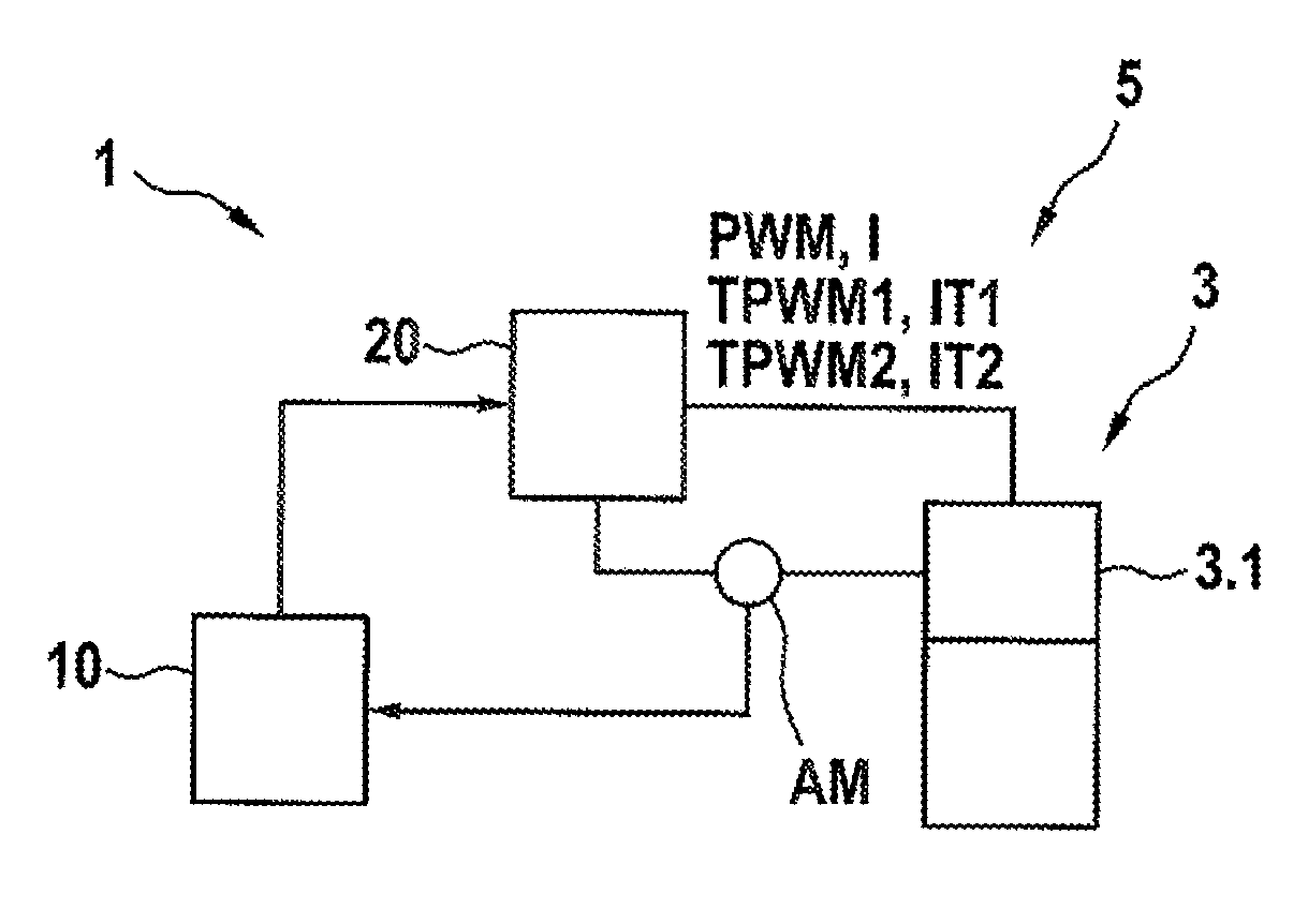
[0017]As can be seen from FIG. 1, a hydraulic assembly 5 has at least one solenoid valve 3 and at least one apparatus 1 for driving a solenoid valve 3. In the exemplary embodiment illustrated, the apparatus 1 for driving a solenoid valve 3 comprises an evaluation and control unit 10, a PWM apparatus 20 and a current measuring apparatus AM. In normal operation, the evaluation and control unit 10 generates a PWM signal PWM having a duty ratio TV and emits said PWM signal to a magnet assembly 3.1 of the solenoid valve 3 by means of the PWM apparatus 20. The current measuring apparatus AM detects a current I through the magnet assembly 3.1 or through a magnet coil (not illustrated in any more detail) of the magnet assembly resulting from the PWM signal PWM and reports the value of the detected current I back to the evaluation and control circuit 10, wherein a current I that is above a response threshold of the magnet assembly 3.1 triggers a switching process of the solenoid valve 3. In ...


PUM


Abstract

The invention relates to an apparatus (1) and a method for driving a solenoid valve (3), having an evaluation and control unit (10), a PWM apparatus (20) and a current measuring apparatus (AM), wherein, in normal operation, the evaluation and control unit (10) generates a PWM signal (PWM) having a duty ratio (TV) and emits said PWM signal to a magnet assembly (3.1) of the solenoid valve (3) by means of the PWM apparatus (20), wherein the current measuring apparatus (AM) detects a current (I) through the magnet assembly (3.1) resulting from the PWM signal (PWM) and reports said current back to the evaluation and control circuit (10), wherein a current (I) that is above a response threshold of the magnet assembly (3.1) triggers a switching process of the solenoid valve (3), and wherein, in test operation, the evaluation and control circuit (10) generates and emits at least one test PWM signal (TPWM1, TPWM2) having a duty ratio (TV1, TV2) by means of the PWM apparatus (20), said at least one test PWM signal inducing a test current (IT1, IT2) that is below the response threshold through the magnet assembly (3.1), and to a hydraulic assembly having such an apparatus (1) for driving a solenoid valve (3). In this case, in test operation, the evaluation and control unit (10) generates and emits at least two different test PWM signals (TPWM1, TPWM2) and detects the resulting test currents (IT1, IT2), wherein the evaluation and control unit (10) derives presently prevailing ambient conditions from the predefined test PWM signals (TPWM1, TPWM2) and the resulting test currents (IT1, IT2) and, in normal operation, generates and emits a subsequent PWM signal (PWM) based on the presently prevailing ambient conditions, said subsequent PWM signal inducing a current (I) that is above the response threshold, for the purpose of switching the solenoid valve (3).

Description

[0001]The invention proceeds from an apparatus or a method for driving a solenoid valve of the generic type of independent claims 1 or 7. The subject matter of the present invention is also a hydraulic assembly having such an apparatus for driving a solenoid valve of the generic type of independent patent claim 6.[0002]The prior art discloses apparatuses and methods for driving solenoid valves used in hydraulic brake systems having ABS and / or ESP functionality. Solenoid valves of this kind are embodied, in particular, as normally closed or normally open high-pressure switching valves and comprise a magnet assembly having a magnet coil, the magnetic force of which is generated by means of the electric current through the magnet assembly or the magnet coil. As a technical component, a solenoid valve serves to monitor the inlet or outlet of fluids or to control and to regulate the flow direction. The electric currents for driving the solenoid valves can be regulated or controlled here....

Claims


Application Information

Patent Timeline
IPC IPC(8): F16K31/06B60T8/34B60T8/36
CPCF16K31/06B60T8/341B60T8/363B60T8/36B60T8/171B60T8/885B60T2270/406H01F7/18B60T8/17
Inventor GARDT, ANDREJEISELE, CHRISTOPHSCHUBITSCHEW, VALENTINEDELMANN, VOLKER
Owner ROBERT BOSCH GMBH
Why Eureka
Try Eureka