
Voltage regulation circuit for an RFID circuit

Active Publication Date: 2018-06-21
EM MICROELECTRONIC-MARIN
View PDF0 Cites 4 Cited by
  • Summary
  • Abstract
  • Description
  • Claims
  • Application Information

AI Technical Summary

Benefits of technology

The patent text describes a circuit that regulates voltage, which can reduce the flow of current and prevent damage to electronics. It also reduces the output of fluctuations and ripples. The circuit uses a minimum number of active components, making it cost-effective and space-saving.

Problems solved by technology

However, such a limiter can be rather inefficient.
It may waste power and / or it may induce a large amount of fluctuations or ripples on an output electrically connected to the logic unit or processor.
One deficiency of a limiter-based voltage regulation for an RFID circuit is that during an amplitude modulation (AM modulation) the incoming RF signal is switched on and off to encode data for the RFID circuit.
Additionally, the rectifier may exhibit a reverse current leakage that may also siphon energy away from the recovered DC voltage during the time period when no RF incoming signal is present.
Also due to the switching action of the RF input signal and the limited bandwidth of the limiting circuitry comparatively large fluctuations or ripples may be induced onto the DC output signal.
Such fluctuations or ripples may cause problems with sensitive analogue circuitry of the RFID circuit or RFID tag.
Such fluctuations or ripples on the DC output of the regulator or limiter become even worse when the incoming RF field is comparatively strong.
Such a solution is limited in bandwidth and with regard to so called headroom losses.
The implementation of numerous LDOs involves four active circuits that may add complexity, die array and increased current consumption.

Method used


Image

  • Voltage regulation circuit for an RFID circuit
  • Voltage regulation circuit for an RFID circuit
  • Voltage regulation circuit for an RFID circuit

Examples


Embodiment Construction

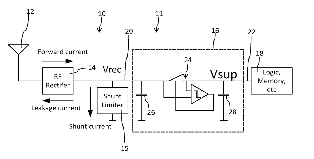
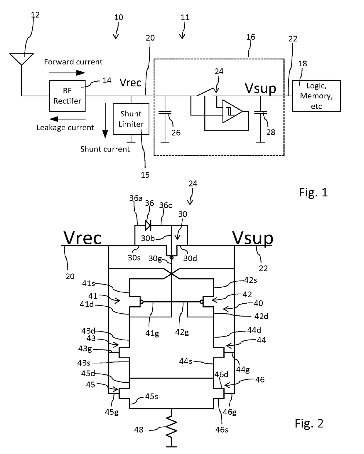
[0046]In FIG. 1, a schematic block diagram of an RFID circuit 10 is illustrated. The RFID circuit 10 comprises an antenna 12 and an RF front end 11. The RF front end 11 comprises a rectifier circuit 14, a limiter 15 and a voltage regulation circuit 16. The voltage regulation circuit 16 is only illustrated in dashed lines. The voltage regulation circuit 16 comprises an input 20 connected to the rectifier circuit 14. The voltage regulation circuit 16 comprises an output 22 connected to a digital unit, namely to a logic unit or processor 18 of the RFID circuit 10. The RFID circuit 10 comprises the RF-front end 11 and the logic unit 18, the latter of which typically comprising a processor and a memory. The voltage regulation circuit 16 is configured to provide a DC driving voltage to the logic unit or processor 18, which DC voltage is derived from an RF input voltage received by the antenna 12.

[0047]The voltage regulation circuit as shown in FIG. 1 comprises an input 20 connected to bot...


PUM


Abstract

The present invention relates in one aspect to a voltage regulation circuit for an RFID circuit (10), the voltage regulation circuit comprising:an input (20) connectable to a rectifier circuit (14),an output (22) connectable to a processor (18) of the RFID circuit,at least one switch (24) arranged between the input (20) and the output (22) and connected to the input (20) and the output (22), wherein the switch (24) is capable to electrically connect the output (22) to the input (20) and to disconnect the output (22) from the input (20).

Description

TECHNICAL FIELD[0001]The present invention relates to the field of RFID circuits, in particular to the field of RFID transponders such as passive or active RFID transponders. In one aspect the invention relates to a voltage regulation circuit of an RFID circuit, wherein the voltage regulation circuit is configured to limit and / or to regulate a driving voltage for a logic unit or processor of the RFID transponder. Moreover, the voltage regulation circuit is configured to derive a driving voltage for a logic unit or processor that is derived from an external RF field.BACKGROUND OF THE INVENTION[0002]With RFID transponders, such as RFID tags a rectifier is used to extract electrical energy out of an incoming RF signal. The rectifier is used to convert the RF energy into a DC voltage that is configured to power a digital unit or logic unit or to power a processor of the RFID circuit. Common architectures for rectifiers use a Dickson-style charge pump and cascade multiple stages together...

Claims


Application Information

Patent Timeline
IPC IPC(8): G06K19/07
CPCG06K19/0723G05F1/56G05F3/24G05F3/262G06K19/0701
Inventor BUESCHER, KEVIN SCOTT
Owner EM MICROELECTRONIC-MARIN
Learn More