

Isolated synchronous rectification-type dc/dc converter
a technology of dc/dc converter and synchronous rectification, which is applied in the direction of electric variable regulation, process and machine control, instruments, etc., can solve the problem that the same problem may occur even in other protection circuits, and achieve the effect of reducing the circuit area and keeping the characteristics of the circuit elements uniform
- Summary
- Abstract
- Description
- Claims
- Application Information
AI Technical Summary
Benefits of technology
Problems solved by technology
Method used
Image

Examples
first embodiment
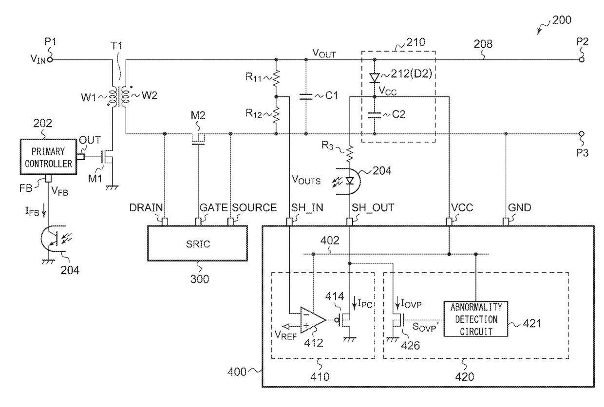
[0084]FIG. 3 is a circuit diagram of an isolated DC / DC converter 200 according to a first embodiment. The DC / DC converter 200 is a flyback converter, receives an input voltage VIN at an input terminal P1 thereof, generates an output voltage VOUT of direct current stabilized to a predetermined target voltage, and supplies the output voltage VOUT to a load connected between an output terminal P2 and a ground terminal P3 (not illustrated).
[0085]A transformer T1 has a primary winding W1 and a secondary winding W2. One end of the primary winding W1 is connected to the input terminal P1 and receives the DC input voltage VIN. A drain of the switching transistor M1 is connected to the other end of the primary winding W1 of the transformer T1. A sense resistor for current detection may be inserted between a source of the switching transistor M1 and a ground line.
[0086]A synchronous rectification transistor M2 and the secondary winding W2 of the transformer T1 are provided in series between t...
first configuration example
[0118]FIG. 6 is a circuit diagram illustrating a first configuration example (200A) of the DC / DC converter.
[0119]A protection circuit 420A is an over-voltage protection (OVP) circuit. The power supply voltage VCC is supplied to an over-voltage protection (OVP) pin of a secondary controller 400A via a resistor R31. The voltage VCC′, obtained by dividing the power supply voltage VCC by an external resistor R31 and a built-in resistor R32 is generated at the OVP pin. The resistor R32 may be an externally-attached part.
[0120]As described above, VCC≈VOUT during a switching operation of the DC / DC converter 200A, and thus, the voltage VCC′ of the VCC pin is a voltage corresponding to the output voltage VOUT. When the voltage VCC′ of the OVP pin exceeds the predetermined over-voltage threshold value VOVP, the protection circuit 420A generates the current IOVP and drives the photocoupler 204.
[0121]The protection circuit 420A is configured to maintain a drive state of the photocoupler 204 unt...
second embodiment
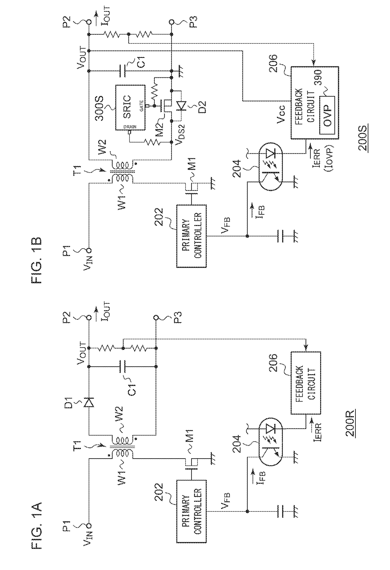
[0150]A problem to be solved by a second embodiment will be described. The inventors of the present application have conducted studies regarding the flyback converter 200S of FIG. 1B, and as a result, has recognized the following problem. The output voltage VOUT (or the power supply voltage VCC originating therefrom) is supplied to the power supply (VCC) pin of the feedback circuit 206, and an internal circuit of the feedback circuit 206 operates using this output voltage VOUT as a power supply voltage.
[0151]When the VCC pin is detached from the substrate or a wiring on the substrate is disconnected (these cases are referred to as open abnormalities), the output voltage VOUT is no longer supplied to the VCC pin, the feedback circuit 206 becomes inoperable, and eventually, the output voltage VOUT becomes uncontrollable.
[0152]The same problem may occur in a diode rectification-type flyback converter, which includes a rectifier diode instead of the synchronous rectification transistor ...
PUM
 Abstract
Description
Claims
Application Information