Polarizing plate, method of manufacturing the same, and optical apparatus

a technology of polarizing plate and manufacturing method, which is applied in the direction of polarizing elements, instruments, optics, etc., can solve the problems of narrow grid width, difficult to maintain reliability as a polarizing plate, and difficulty in actually forming a pattern where the grid width is narrowed, and achieve excellent controllability of reflectance characteristics and transmittance characteristics. high

Active Publication Date: 2018-06-28
DEXERIALS CORP
View PDF13 Cites 10 Cited by
  • Summary
  • Abstract
  • Description
  • Claims
  • Application Information

AI Technical Summary

Benefits of technology

[0023]According to the present invention, it is possible to provide a polarizing plate having high transmittance characteristics and excellent controllability of reflectance characteristics, a method of manufacturing the polarizing plate, and an optical apparatus including the polarizing plate.

Problems solved by technology

However, from the viewpoint of, for example, increasing variations in manufacturing and the like, it is difficult to actually form a pattern where the grid width is narrowed, and it is difficult to maintain reliability as a polarizing plate.

Method used


Image

  • Polarizing plate, method of manufacturing the same, and optical apparatus
  • Polarizing plate, method of manufacturing the same, and optical apparatus
  • Polarizing plate, method of manufacturing the same, and optical apparatus

Examples


examples

[0099]Next, examples of the present invention will be described, but the present invention is not limited to these examples.

examples 1 and 2

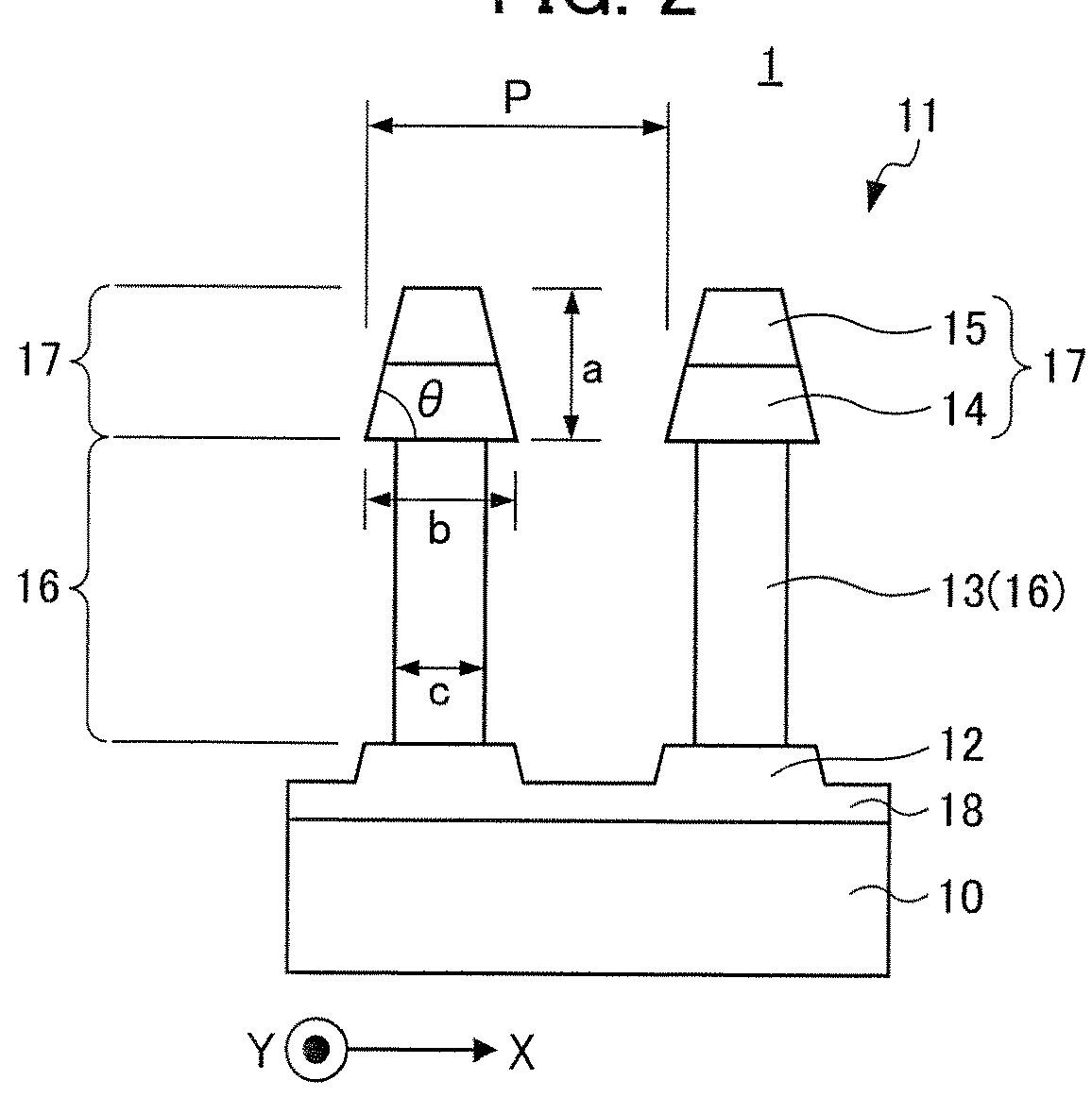
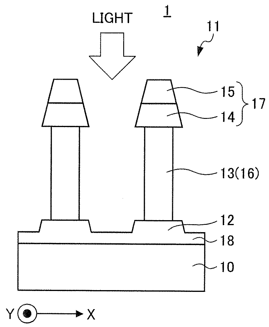
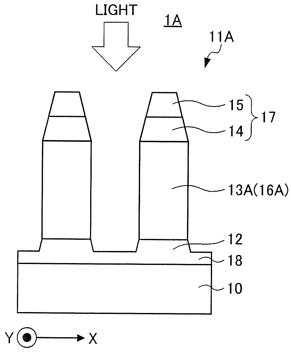
[0100]In Example 1, the polarizing plate 1 having the structure illustrated in FIG. 1 was used for simulation. In addition, in Example 2, the polarizing plate 1A having the structure illustrated in FIG. 4 was used for simulation. More specifically, the optical characteristics of these polarizing plates were verified by electromagnetic field simulation in accordance with a rigorous coupled wave analysis (RCWA) method. For the simulation, a grating simulator Gsolver produced by Grating Solver Development was used. In addition, the simulation of other Examples described below is the same.

[0101]FIG. 5 is a graph illustrating results of simulation verification of the transmission-axis transmittance Tp of the polarizing plate 1 having the structure illustrated in FIG. 1 and the polarizing plate 1A having the structure illustrated in FIG. 4. In FIG. 5, the horizontal axis represents the wavelength λ (nm), and the vertical axis represents the transmission-axis transmittance Tp (%). Herein, ...

example 3

[0103]In Example 3, the polarizing plate 1 having the structure illustrated in FIG. 1, of which the grid width was changed to 35 nm, 40 nm, 45 nm, 50 nm, and 55 nm and of which the ratio of the width of the reflection layer to the grid width was changed was used for simulation. More specifically, simulation was performed for light in the green band (wavelength λ=520 to 590 nm) of incident light.

[0104]FIG. 6 is a graph illustrating results of simulation verification of the relationship between the width of the reflection layer of the polarizing plate 1 having the structure illustrated in FIG. 1 and the transmission-axis transmittance Tp. More specifically, FIG. 6 illustrates the relationship between the ratio of the width of the reflection layer to the grid width and the transmission-axis transmittance Tp. The horizontal axis represents the width ratio (%) of the reflection layer, and the vertical axis represents the transmission-axis transmittance Tp (%). In addition, FIG. 7 is a gr...


PUM


Abstract

Provided are a polarizing plate having high transmittance characteristics and excellent controllability of reflectance characteristics, a method of manufacturing the polarizing plate, and an optical apparatus including the polarizing plate. A polarizing plate having a wire grid structure includes a transparent substrate and grid-shaped protrusions that are arranged on the transparent substrate at a pitch shorter than a wavelength of light in a use band and extend in a predetermined direction, the grid-shaped protrusion includes, in order from the transparent substrate side, a pedestal, a reflection layer, a dielectric layer, and an absorption layer, and the pedestal has a trapezoidal shape when viewed from the extending direction of the grid-shaped protrusions.

Description

[0001]This application is based on and claims the benefit of priority from Japanese Patent Application No. 2016-255934, filed on 28 Dec. 2016, the content of which is incorporated herein by reference.BACKGROUND OF THE INVENTIONField of the Invention[0002]The present invention relates to a polarizing plate, a method of manufacturing the polarizing plate, and an optical apparatus.Related Art[0003]In the related art, it is known that, in a wire grid type polarizing plate, in principle, transmittance of light is decreased toward a short wavelength side on the basis of a relationship between a pitch and a grid width (width in an arrangement direction of a grid) according to a wavelength of light in a use band. Particularly, in a visible light region (red band: wavelength λ=600 to 680 nm, green band: wavelength λ=520 to 590 nm, and blue band: wavelength λ=430 to 510 nm) used in a liquid crystal projector, the blue band has the lowest transmittance.[0004]Meanwhile, it is known that the tra...

Claims


Application Information

Patent Timeline
Patent Type & Authority Applications(United States)
IPC IPC(8): G02B5/30G02B1/18
CPCG02B5/3058G02B1/18G02B5/3033G02B1/14
Inventor TAKEDA, TOMU
Owner DEXERIALS CORP
Why Eureka
Try Eureka