Electric double-layer device

a double-layer device and electric double-layer technology, applied in the direction of electrolytic capacitors, hybrid capacitor terminals, transportation and packaging, etc., can solve the problems of narrow potential window and decomposition, and achieve the effects of preventing leakage of positive ions, reducing the potential of decomposition, and increasing the lifespan of electric double-layer devices

Active Publication Date: 2018-06-28
MAXWELL TECH KOREA CO LTD
View PDF4 Cites 0 Cited by
  • Summary
  • Abstract
  • Description
  • Claims
  • Application Information

AI Technical Summary

Benefits of technology

[0054]According to the present invention, an electric double layer device further includes a urethane potting unit for filling the gap between a first terminal and a first through hole and the gap between a second terminal and a second through hole. Consequently, it is possible to completely prevent the leakage of positive ions, whereby the positive ions are prevented from being wetted and thus the lifespan of the electric double layer device is relatively increased.
[0055]According to the present invention, a urethane resin is rapidly and easily introduced into a first pot recess and a second pot recess defined by a volume protrusion, which protrudes upward, of a rubber cap such that the first pot recess and the second pot recess are lower in position than the volume protrusion. Consequently, it is possible to maximally prevent a phenomenon in which the urethane resin spreads out after being introduced into the first pot recess and the second pot recess while improving workability, whereby the electric double layer device has a neat external appearance.
[0056]According to the present invention, when the urethane resin is introduced into the first pot recess and the second pot recess, the urethane resin rapidly fills a first pocket and a second pocket and is hardened in tight contact with the first terminal and the second terminal, respectively. As a result, it is possible to further completely prevent the leakage of positive ions through the gap between the first terminal and the first through hole and the gap between the second terminal and the second through hole, whereby the lifespan of the electric double layer device is further increased.
[0057]According to the present invention, an aluminum terminal is anodized in advance to form an aluminum oxide film thereon, whereby the lifespan of the electric double layer device is guaranteed.
[0058]According to the present invention, the volume protrusion, which protrudes upward, of the rubber cap has a concave portion, the height of which gradually decreases toward the center thereof such that the concave portion becomes flat even though the center of the volume protrusion rises when the case is beaded, whereby the first terminal and the second terminal are stably loaded on a circuit board when the first terminal and the second terminal are connected to the circuit board.
[0059]According to the present invention, it is possible to increase surface coupling force between each of the first pot recess and the second pot recess and the urethane resin.

Problems solved by technology

However, the electric double layer capacitor 100 using the aqueous electrolyte has problems in that the potential window is narrow and decomposition occurs.

Method used


Image

  • Electric double-layer device
  • Electric double-layer device
  • Electric double-layer device

Examples


Embodiment Construction

[0076]An exemplary embodiment of an electric double layer device according to the present invention will be described in detail with reference to the accompanying drawings. A plurality of embodiments may be provided. The objects, features, and advantages of the present invention will be more clearly understood from the following detailed description of the embodiment.

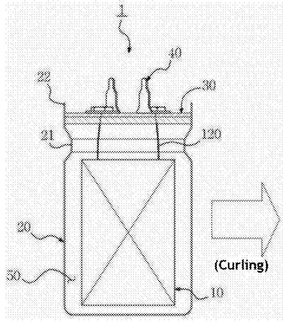
[0077]FIG. 7 is a perspective view showing an electric double layer device according to the present invention, FIG. 8 is an exploded perspective view showing the electric double layer device according to the present invention, and FIG. 9 is a longitudinal sectional view showing the electric double layer device according to the present invention.

[0078]As shown in FIGS. 7 to 9, the electric double layer device according to the present invention includes a wound electrode unit 10 having a first current collection sheet 11 and a second current collection sheet 12 wound in the state in which the first current collection shee...


PUM


Abstract

Disclosed herein is an electric double layer device including a urethane potting unit (50) for filling the gap between a portion of a first terminal (21) that is exposed out of a rubber cap (40) and a first through hole (41) and the gap between a portion of a second terminal (22) that is exposed out of the rubber cap and a second through hole (42), wherein an aluminum terminal (A) constituting each of the first terminal (21) and the second terminal (22) is anodized such that an aluminum oxide film (Al) is formed on the aluminum terminal, whereby the lifespan of the electric double layer device is relatively increased.

Description

TECHNICAL FIELD[0001]The present invention relates to an electric double layer device, and more particularly to an electric double layer device that has a long lifespan and a neat external appearance.BACKGROUND ART[0002]In general, an electric double layer device is a device that stores electrical energy, such as a battery, a capacitor, or an electrolytic condenser. An electric double layer device is electrically charged and discharged using electrodes that are electrically conductive. Electric double layer devices are used in cellular phones, GPS receivers, MP3 players, and backup memory devices. In addition, electric double layer devices are used in wind energy systems, solar energy systems, and motors of electric vehicles and hybrid electric vehicles.[0003]One example of such an electric double layer device may be a capacitor.[0004]In the electric double layer capacitor, an electrostatic layer is formed at the interface between an activated carbon electrode and an organic electro...

Claims


Application Information

Patent Timeline
Patent Type & Authority Applications(United States)
IPC IPC(8): H01G11/28H01G11/70H01G11/78H01G11/74H01G11/46
CPCH01G11/28H01G11/70H01G11/78H01G11/74H01G11/46H01G11/80H01G11/82Y02T10/70Y02E60/13
Inventor SHIN, NA RIYOO, SUNG WOOKLEE, KYU JEUNGKIM, YOUNG JINAHN, HYUNG SIKCHOI, JUNG HOCHOI, YOUNG SEG
Owner MAXWELL TECH KOREA CO LTD
Why Eureka
Try Eureka