Composite material preparation system and method effectively improving composite material interface bonding

a composite material and interface bonding technology, applied in the field of synthetic materials, can solve the problems of high cost, low yield, and inability to meet actual needs of traditional single-phase materials, and achieve excellent interface bonding and effective improvement of the interface bonding of composite materials

Active Publication Date: 2018-07-05
SHAANXI UNIV OF SCI & TECH
View PDF0 Cites 1 Cited by
  • Summary
  • Abstract
  • Description
  • Claims
  • Application Information

AI Technical Summary

Benefits of technology

[0007]In view of the above-mentioned issues in the prior art, the technical problem to be solved by the present application is to provide a composite material preparation system and a composite material preparation method, effectively improving the interface bonding of the composite material, in which a composite material with an excellent interface bonding is prepared, taking advantage of the characteristics of the reactants themselves being heated at a controllable temperature and pressure by induction heating.

Problems solved by technology

In many fields, the performance of traditional single-phase materials cannot meet actual needs, which has prompted people to study and prepare composite materials consisting of multiple phases to improve the performance thereof [Xiya ZHOU, “COMPOSITE MATERIAL,” Chemical Industry Press, Beijing].
The nanocomposites prepared by these methods have some advantages, such a, clean surfaces, no impurities, particle controllability, and high activity, but currently the yield is relatively low and the cost is high.
Although these methods have a high yield, the prepared composite material contains certain impurities.
When preparing a composite material by these methods, the matrix material and the reactants are simultaneously heated by the third-party material, the formation of the interface is completely random, without being guided, and the distribution of the reactants on the matrix material is not uniform and the interface bonding is poor.
It is apparent that this process is complex, and difficult to apply to industrial production.

Method used


Image

  • Composite material preparation system and method effectively improving composite material interface bonding
  • Composite material preparation system and method effectively improving composite material interface bonding
  • Composite material preparation system and method effectively improving composite material interface bonding

Examples


example 1

[0078]Step 1: 0.012 mol of potassium permanganate is dissolved in 30 ml of distilled water, with magnetic stirring for 30 minutes to obtain a 0.4 mol / L of potassium permanganate solution;

[0079]Step 2: 0.012 mol of phenylpropionaldehyde is dissolved in 30 ml of distilled water, with magnetic stirring for 30 minutes to obtain a 0.4 mol / L of phenylpropionaldehyde solution;

[0080]Step 3: the potassium permanganate solution and the phenylpropionaldehyde solution are mixed and magnetically stirred for 30 minutes to obtain a reaction precursor solution C;

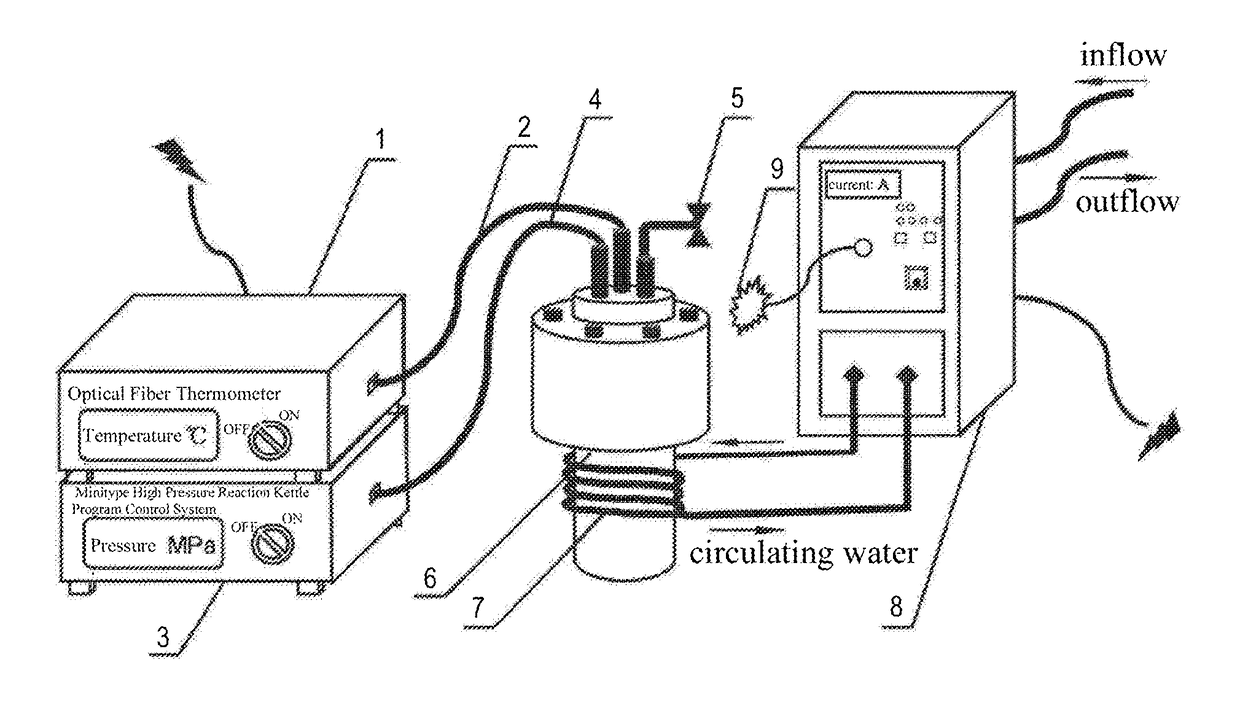
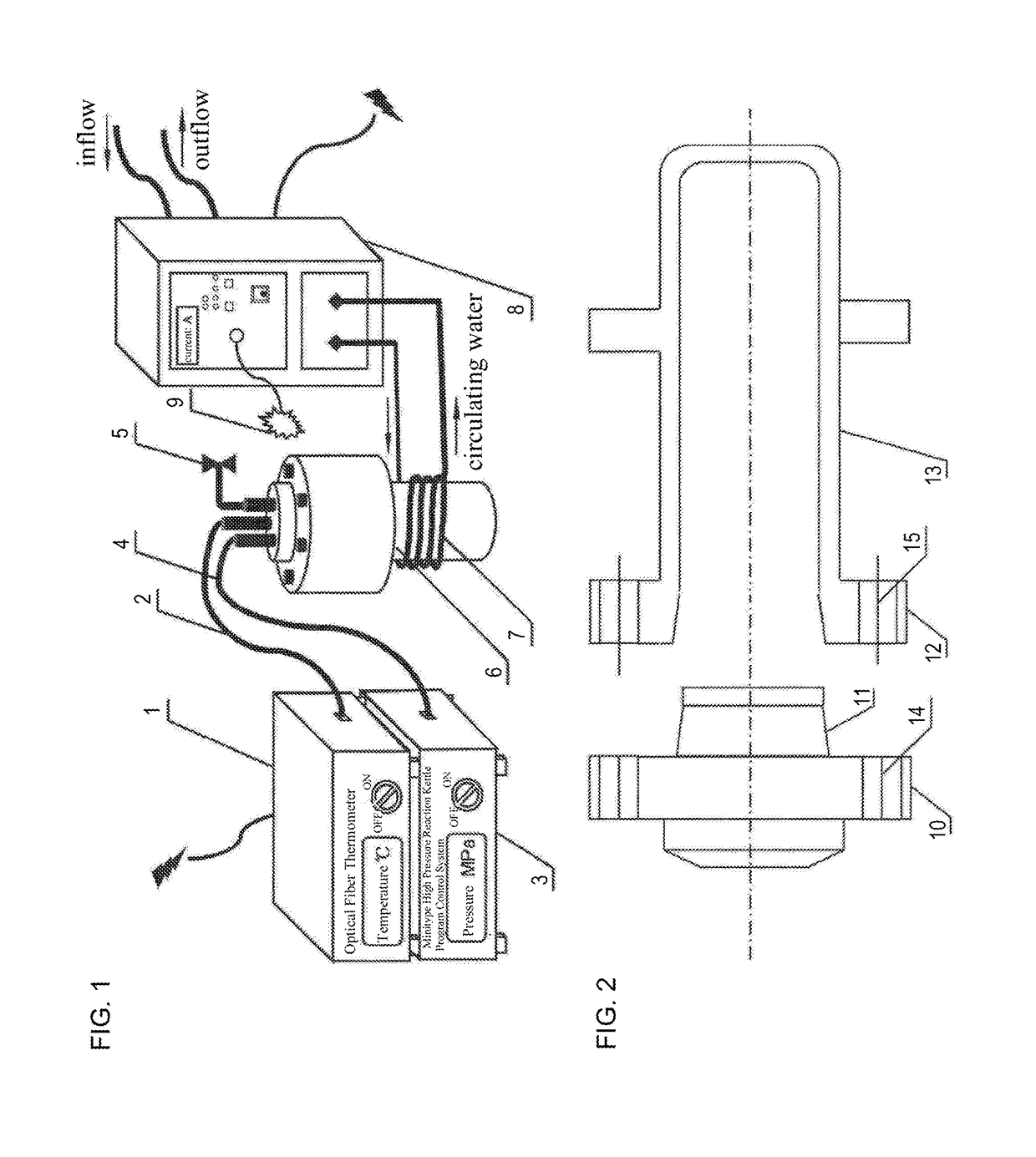
[0081]Step 4: the precursor solution C is transferred to a reaction kettle, to which graphite sheets capable of sensing an alternating magnetic field is added. The reaction kettle is sealed and placed in a hydrothermal induction heating device for reaction for 24 hours under an induction frequency of 50 kHz and an output current of 200 A, then naturally cooled to room temperature;

[0082]Step 5: the compound product is separated from the susp...

example 2

[0083]Step 1: 0.015 mol of potassium permanganate is dissolved in 30 ml of distilled water, with magnetic stirring for 50 minutes to obtain a 0.5 mol / L of potassium permanganate solution;

[0084]Step 2: 0.015 mol of phenylpropionaldehyde is dissolved in 30 ml of distilled water, with magnetic stirring for 50 minutes to obtain a 0.5 mol / L of phenylpropionaldehyde solution;

[0085]Step 3: the potassium permanganate solution and the phenylpropionaldehyde solution are mixed and magnetically stirred for 50 minutes to obtain a reaction precursor solution C;

[0086]Step 4: the precursor solution C is transferred to a reaction kettle, to which graphite sheets capable of sensing an alternating magnetic field is added. The reaction kettle is sealed and placed in a hydrothermal induction heating device for a reaction for 16 hours under an induction frequency of 50 kHz and an output current of 300 A, then naturally cooled to room temperature;

[0087]Step 5: the compound product is separated from the su...

example 3

[0088]Step 1: 0.02 mol of potassium permanganate is dissolved in 30 ml of distilled water, with magnetic stirring for 70 minutes to obtain a 0.67 mol / L of potassium permanganate solution;

[0089]Step 2: 0.02 mol of phenylpropionaldehyde is dissolved in 30 ml of distilled water, with magnetic stirring for 70 minutes to obtain a 0.67 mol / L of phenylpropionaldehyde solution;

[0090]Step 3: the potassium permanganate solution and the phenylpropionaldehyde solution are mixed and magnetically stirred for 70 minutes to obtain a reaction precursor solution C;

[0091]Step 4: the precursor solution C is transferred to a reaction kettle, to which graphite sheets capable of sensing an alternating magnetic field is added. The reaction kettle is sealed and placed in an induction heating device for a reaction for 10 hours under an induction frequency of 50 kHz and an output current of 400 A, then naturally cooled to room temperature;

[0092]Step 5: the compound product is separated from the suspension aft...


PUM


Abstract

A composite material preparation system comprises a sealed reaction kettle for containing reactants and base materials; temperature and pressure detecting units for detecting the temperature and pressure inside the reaction kettle; and a heating unit for hydrothermally induced heating, based on the detected temperature and pressure values. The heating unit comprises an induction coil, an induction heating device, and a control mechanism for controlling the generation of an induction frequency of the induction heating device. The reaction kettle is located in the induction coil, both ends of the induction coil are mounted on an outer wall of the induction heating device, and the induction coil and the induction heating device have circulating water introduced inside. The device can prepare a composite material having good interface bonding, by utilizing induced heating under the premise of controllable temperature and pressure, and by utilizing the characteristic that the reactants themselves are heated.

Description

FIELD OF THE INVENTION[0001]The present application belongs to the field of material synthetic technology, and relates to a composite material preparation system and method capable of effectively improving the interface bonding of a composite material.BACKGROUND OF THE INVENTION[0002]With the rapid development of cutting-edge science and technology, the requirements for material performance are increasing. In many fields, the performance of traditional single-phase materials cannot meet actual needs, which has prompted people to study and prepare composite materials consisting of multiple phases to improve the performance thereof [Xiya ZHOU, “COMPOSITE MATERIAL,” Chemical Industry Press, Beijing].[0003]However, to realize a “1+1>2” synergistic effect of a composite material, the interface thereof is crucial. In order to obtain excellent interface bonding, some methods have been widely used, such as surface treatment of the reinforcement (such as chemical corrosion, ray irradiatio...

Claims


Application Information

Patent Timeline
Patent Type & Authority Applications(United States)
IPC IPC(8): B01J19/08B01J19/10B01J19/18B01J19/02B01J19/00
CPCB01J19/087B01J19/10B01J19/1875B01J19/02B01J19/0066B01J19/0013B01J2219/00139B01J2219/00162B01J2219/0854B01J2219/0871B01J2219/0877B01J2219/0888B01J19/0006B01J19/0053B01J19/18B01J2219/0803B01J2219/0009B01J2219/0295
Inventor HUANG, JIANFENGLI, WENBINLI, RUIZILI, JIAYINFEI, JIEOUYANG, HAIBOCAO, LIYUNLI, DUOZHOU, LEI
Owner SHAANXI UNIV OF SCI & TECH
Why Eureka
Try Eureka