Oil distribution element

a technology of distribution element and oil, which is applied in the direction of electrical apparatus, dynamo-electric machines, cooling/ventilation arrangement, etc., can solve the problems of large pressure loss, difficult implementation of these concepts, and the need for coolant pumps, so as to reduce the amount of mass to be moved rotationally, light design, and increase the surface area available

Active Publication Date: 2018-07-05
THYSSENKRUPP PRESTA TECCENTER AG
View PDF4 Cites 6 Cited by
  • Summary
  • Abstract
  • Description
  • Claims
  • Application Information

AI Technical Summary

Benefits of technology

[0024]The sudden increase in cross-section within the hollow shaft guarantees a particularly light design and a tremendous increase in the surface area available for heat transfer. It is advantageous that the cooling fluid is guided to the inner surface of the cylindrical shaft cavity in targeted manner and there can flow along the active sheet-metal packet to be cooled, particularly close to it. It is evident t

Problems solved by technology

Such compulsory guides bring about a great pressure loss, caused by the flow resistance, so that coolant pumps become necessary, particularly if a flow direction opposite to centrifugal force is included.
Furthermore, implementation of these concepts is particularly complicated because of the great number of bores, particularly axial hole bores.
However, it has been shown that it is not possible to conduct a sufficient amount of heat away in this manner.
Ultimately, all known cooling devices have one of the following disadvantages:

Method used


Image

  • Oil distribution element
  • Oil distribution element
  • Oil distribution element

Examples


Embodiment Construction

[0026]Embodiments of the rotor equipped according to the invention will be explained in greater detail below, using the figures. These show:

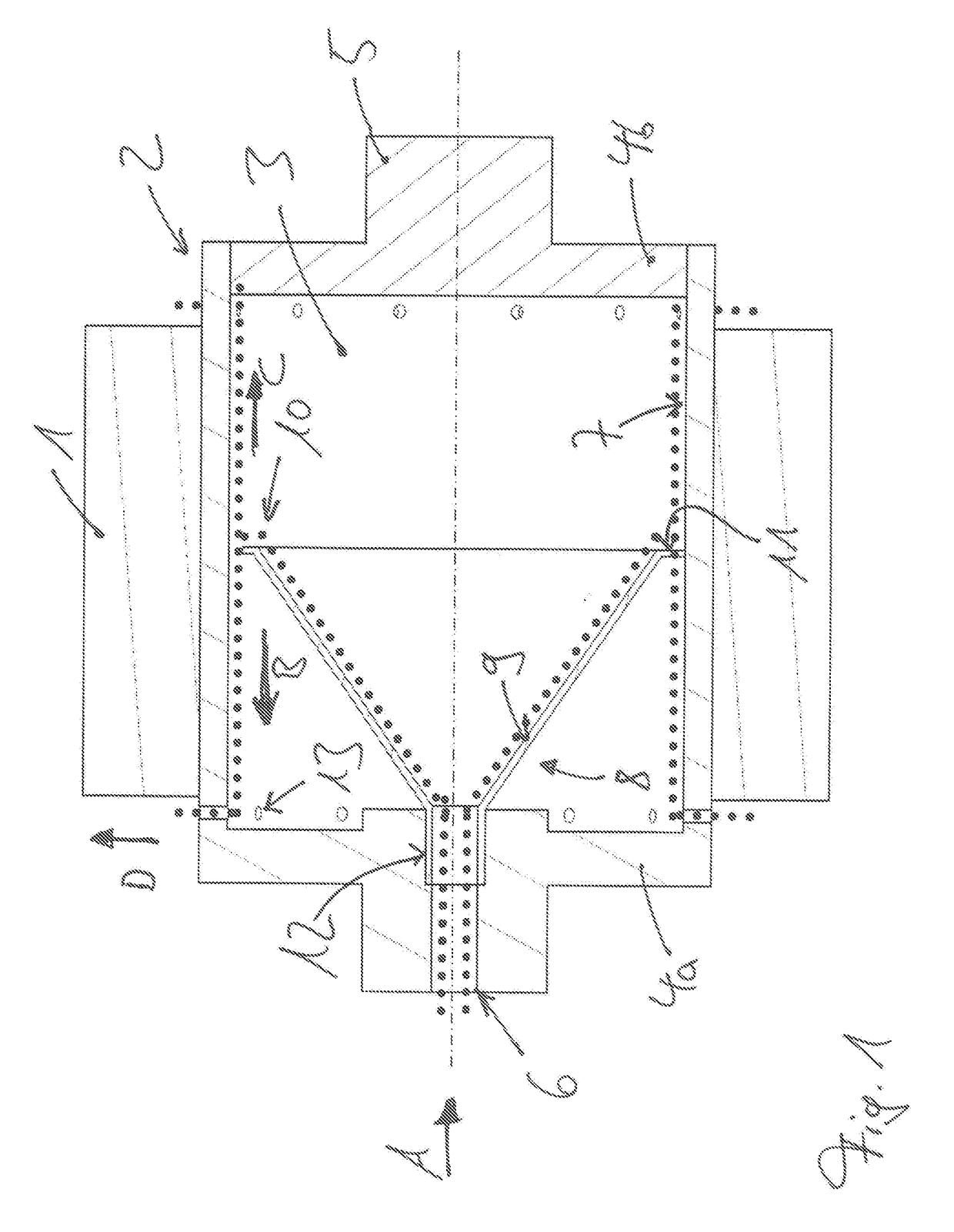
[0027]FIG. 1 a rotor-integrated cooling system, and

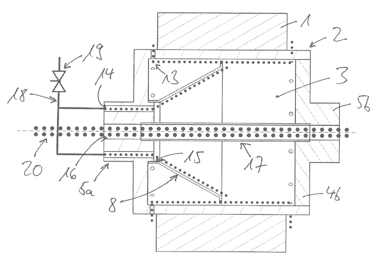
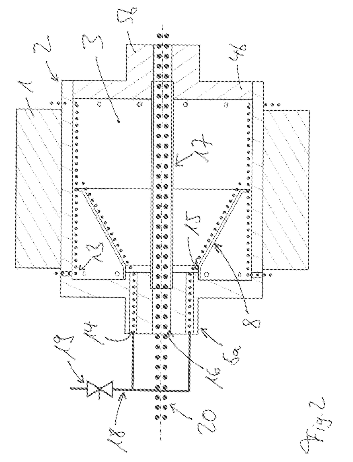
[0028]FIG. 2 a rotor-integrated cooling system with separate media transport.

[0029]In FIG. 1, first a rotor for an electrical machine, particularly for an asynchronous motor or a permanently excited synchronous machine, is shown, which has a hollow rotor shaft equipped with bundles of laminations 1. The hollow rotor shaft is formed by a cylinder barrel 2, which encloses a shaft cavity 3 and is closed off, on both sides, by face flanges 4. In the present case, the one face flange 4a is formed on the cylinder barrel 2, while the other face flange 4b is fitted into the cylinder barrel 2. A shaft journal 5 is provided at both face flanges 4, in each instance, which journal is formed on or attached as a separate component. In one of the shaft journals 5, an inlet 6 is provided, by way of which a cool...


PUM


Abstract

A hollow rotor shaft for a rotor of an electrical machine may include a cylinder barrel closed off by face flanges on both sides. The cylinder barrel may enclose a shaft cavity. A shaft journal may be configured on each face flanges. An inlet may be disposed in one of the shaft journals by way of which a cooling fluid may pass into the shaft cavity and onto an inner surface of the cylinder barrel. A distribution element may be disposed in the shaft cavity. The distribution element may receive the cooling fluid that enters through the inlet, conduct the cooling fluid in a direction of the inner surface of the cylinder barrel by way of a rotation-symmetrical drainage surface, and give off the cooling fluid to the inner surface by way of a mouth region.

Description

[0001]The invention relates to a hollow rotor shaft for the rotor of an electrical machine, having a cylinder barrel closed off on both sides by face flanges, which cylinder barrel encloses a hollow shaft space, wherein a shaft journal is situated at the face flanges, in each instance, and wherein an inlet is provided in one of the face flanges, particularly in the shaft journal, by way of which inlet a cooling fluid gets into the hollow shaft space and to the inner surface of the cylinder barrel.STATE OF THE ART[0002]A plurality of such rotors for electrical machines, having metal sheets laminations disposed on them, which are generally combined into bundles, is known from the state of the art. They are used, for example, in asynchronous machines and in permanently excited synchronous machines. All electrical machines are greatly heated during operation, because of the electromagnetic activity in the rotor and as the result of the heat transfer to other weight-optimized supporting ...

Claims


Application Information

Patent Timeline
IPC IPC(8): H02K7/00H02K9/10H02K9/19
CPCH02K7/003H02K9/10H02K9/19H02K9/193
Inventor PAUL, DANIELKOTSCHAU, CHRISTIAN
Owner THYSSENKRUPP PRESTA TECCENTER AG
Why Eureka
Try Eureka