
Dental suction arrangement

a dental and suction arrangement technology, applied in the field of dental suction arrangement, can solve the problems of limited possibilities, limited ability to safely isolate an operating area from saliva, and neither able to absorb saliva and water, and achieve the effect of effective absorption of saliva and other fluids

Inactive Publication Date: 2018-07-12
ASUM THOMAS
View PDF24 Cites 10 Cited by
  • Summary
  • Abstract
  • Description
  • Claims
  • Application Information

AI Technical Summary

Benefits of technology

The purpose of this invention is to fix issues with the previous way of absorbing saliva and other fluids. The new method is more effective than previous methods.

Problems solved by technology

The problem is that all people look different in combination with the fact that the constructions are rather static with limited possibilities for adjustments of the absorption effect to areas where it is most needed.
These constructions are neither able to absorb saliva and water further down at the bottom of the mouth adjacent to the Glandula Sublingualis nor further back in the throat and they have only limited ability to safely isolate an operating area from saliva since the absorption effect is limited to the area where the suction device's holes are located.
Another major problem is the low comfort of these constructions.
The need to remove saliva and water is often highest at the bottom of the mouth but when the suction device is placed there it almost always will be in contact with the inside of the lower jaw, which is sensitive to pain and it often results in a strong discomfort for the patient or user.
When placing the suction device at the bottom of the mouth, the suction device's holes often get blocked since the mobile part of the mucous membrane is absorbed into the holes and this leads to a removal or to a strong decrease of the device's absorption capacity.
Additionally in such cases, often a loud and very disturbing noise arises when the absorbed mucous membrane vibrates in the suction device's holes.
This results in an incomplete connection with the respective area.
This leads to an unsatisfactory absorption, and is why the advantages in working only with absorption tubes are limited.
The described device can not be placed in the desired area where it is most desired, between the tongue and the teeth row, in an easy way or in a secured fixed position.
It is not protecting the tongue from a rotating instrument or a similar instrument at all.
All common suction devices are today one-sided which are very insufficient when there is a need for keeping both sides dry i. e. during the cementation of a full-arch bridge in the lower jaw where the dry-keeping is essential.
This is an operation of great stress for the dentist and assistant.
Using two ordinary devices would not help then they have to be removed before placing the bridge and then the risk for contaminations is very high.
Another general problem with all different suction devices today are when there is time for i.e. checking and adjusting the height of a crown or a filling it is necessary for the patient to bite together on a occlusion-foil for having a colour-mark on occlusal bad spots.
If the tooth surface is wet the color from the occlusion-foil is not adhering so well to the tooth and the registration becomes false or unsure.
The procedure with repeatedly drying is also very time consuming.
Another dry-keeping problem occur when using modern 3D-laser scanning techniques for taking so called digital impressions of the teeth and teeth-rows.
They have to be saliva-free or else there will be a defect impression not possible to use for producing the prosthetic construction or similar.
This is a problem especially with the lower jaw.
When using today's suction devices where the suction tube is placed over the row of the teeth it will interfere with the recording when scanning a full row in the lower jaw.
A general problem in dentistry is also the noise-level that is generally high due to air-driven high-speed turbines, scalers and the suction devices.
Then the suction devices normally is in action all of the time, especially the “low-volume devices” described here, they are very tiring for the operators staying in this environment all day long.
Also when placed for a long time in the mouth the soft tissue in the mouth will become over-dried resulting in discomfort for the patient.
Another disadvantage of these known cylinder-shaped absorption bodies is that they are placed along the tooth socket.

Method used


Image

  • Dental suction arrangement
  • Dental suction arrangement
  • Dental suction arrangement

Examples


Embodiment Construction

[0118]The invention will now be described in more detail with reference to the attached drawings. Like parts in different embodiments may be described using the same reference numerals.

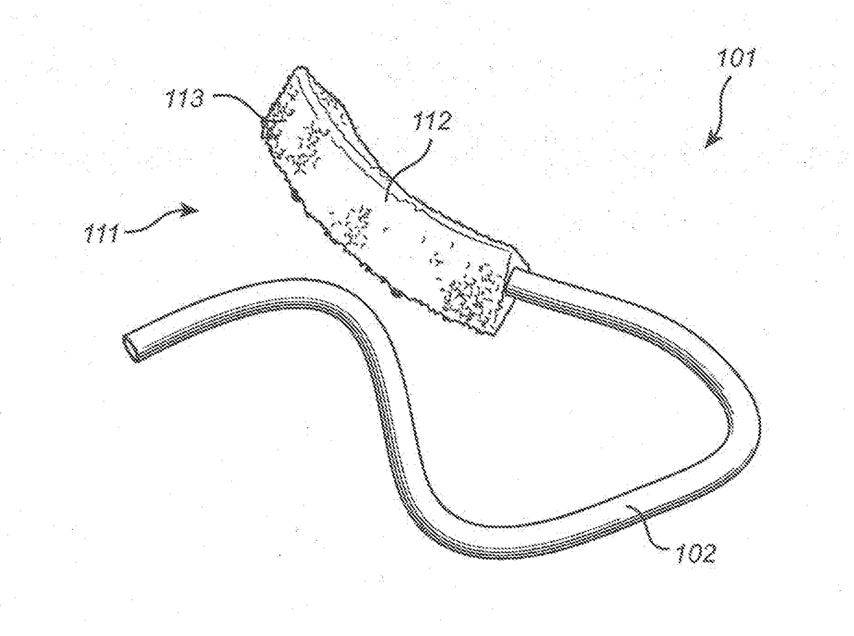
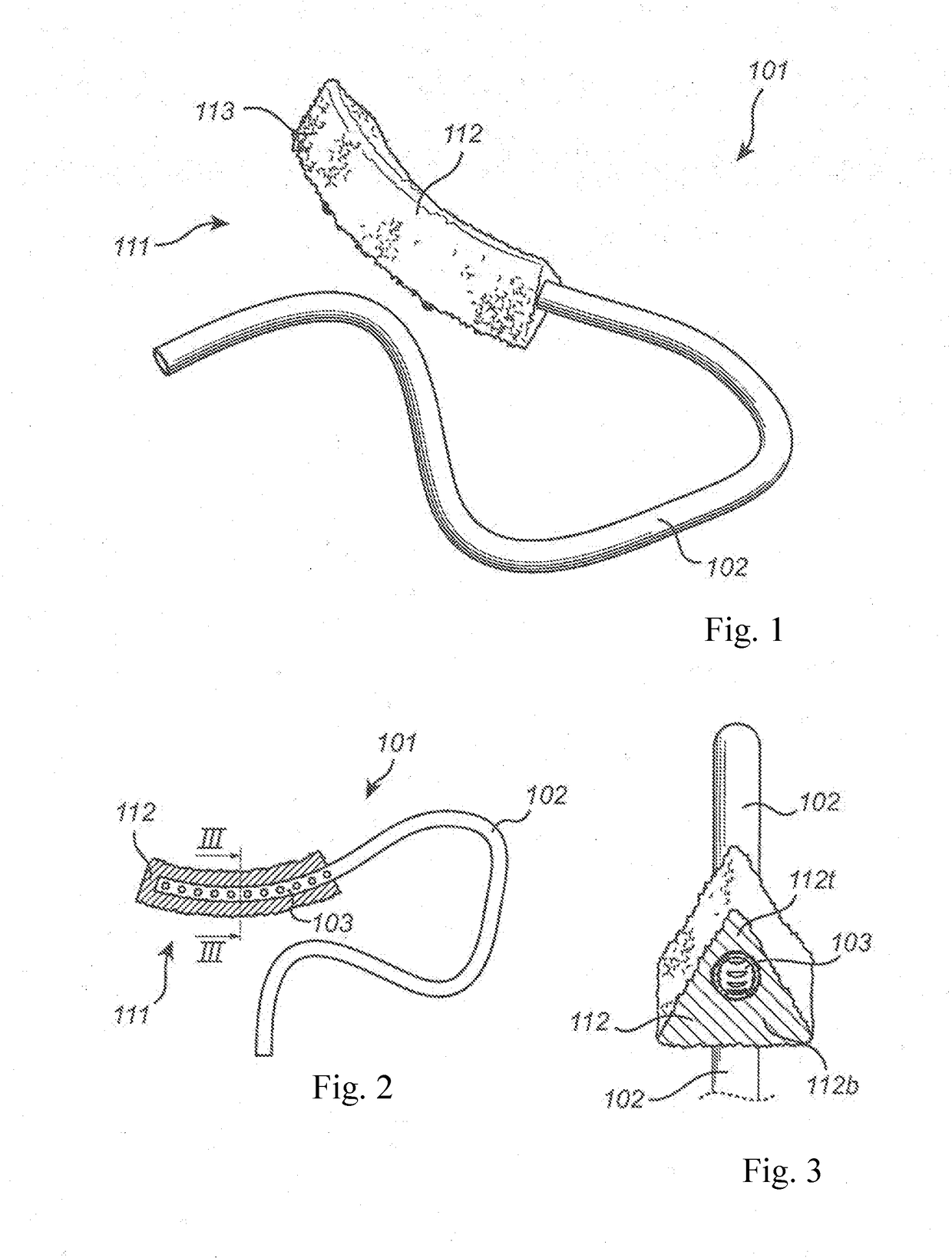
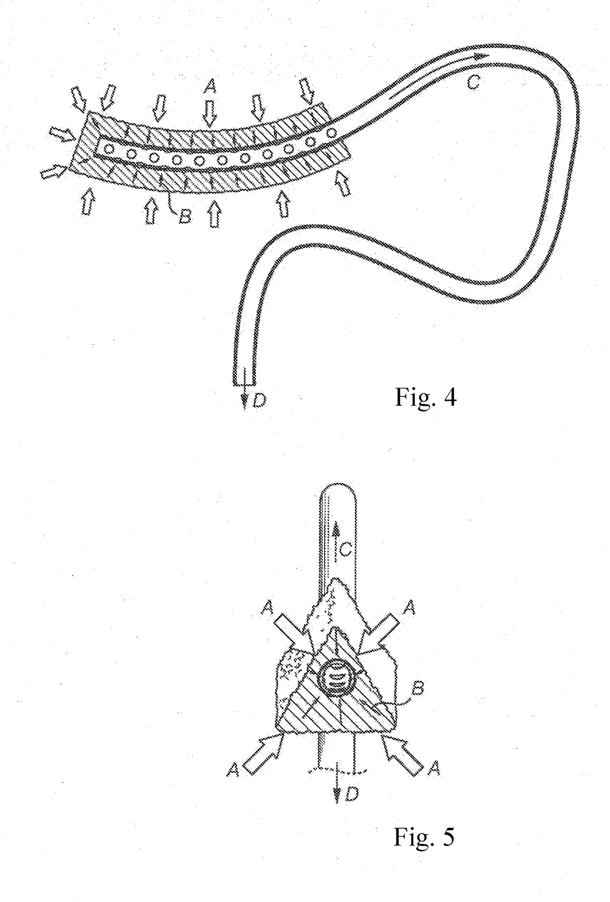
[0119]In FIGS. 1 to 8, a first embodiment of the invention is illustrated. As shown in FIG. 1, the suction device has a suction tube or suction line 101 which can be connected to a vacuum source in order to create a negative pressure inside the suction tube. The suction tube 101 has an exposed part 102 which is visible. The suction tube 101 extends into the absorption body 111 of the suction device with a suction part 103 embedded in the absorption body (not visible in FIG. 1). The absorption body 111 consists of a main part 112, and optionally of an extension part 113. The main part 112 is arranged to be placed at the user's bottom of the mouth between the lower part of the lower jaw and the tongue.

[0120]The extension part 113 is arranged to extend backward from the main part 112 towards the patient'...


PUM


Abstract

A dental suction arrangement which removes saliva and other fluids from a person's oral cavity. The suction arrangement includes a suction tube and an absorption body to be placed in the oral cavity. The suction tube includes a suction part which is arranged in the absorption body and which is equipped with a hole organs or elements communicating with the absorption body. The suction arrangement is made of elastically deformable material in order to adapt to the anatomical shape of the bottom of the mouth.

Description

CROSS-REFERENCE TO RELATED APPLICATIONS[0001]This application is a continuation-in-part application of PCT / EP2016 / 064618 filed on Jun. 23, 2016, which claims priority to Swedish patent application No. 1550893-0 filed on Jun. 26, 2015, and this application is also a continuation-in-part application of U.S. patent application Ser. No. 15 / 538,943, filed Jun. 23, 2016, which claims priority to EP 16205406.8, filed Dec. 12, 2016, all the disclosures of which are incorporated herein by reference in their entiretyTECHNICAL FIELD[0002]The invention is about a dental suction arrangement which removes saliva and other fluids from a person's oral cavity. The suction arrangement includes a suction tube and an absorption body to be placed in the oral cavity, thereby the suction tube includes a suction part which is arranged in the absorption body and which is equipped with a hole organ or hole elements communicating with the absorption body.BACKGROUND[0003]In the dental field different types of ...

Claims


Application Information

Patent Timeline
IPC IPC(8): A61C17/06A61F13/36A61M1/00A61M25/00A61C5/90A61C13/15
CPCA61C17/043A61F13/36A61M1/008A61M25/007A61C5/90A61C19/003A61F2013/4506A61F2013/53726A61C17/08A61C17/096A61C17/10A61M1/84A61C17/06A61C17/092
Inventor ASUM, THOMAS
Owner ASUM THOMAS
Learn More