Device for stimulating tracheobronchial air

Active Publication Date: 2018-07-19
PHYSIO ASSIST
View PDF24 Cites 3 Cited by
  • Summary
  • Abstract
  • Description
  • Claims
  • Application Information

AI Technical Summary

Benefits of technology

The device described in this patent has a feature that allows it to measure the depth and duration of pressure applied to a patient during a respiratory treatment. This information can be used to calculate the average pressure and duration of stimulation applied during multiple cycles of treatment. The device also has a communication module that can send an alert if the average duration of stimulation decreases by at least 20% for a patient. Additionally, the device's microcontroller card can increase the power applied to the negative pressure generator by 10% if the duration of stimulation exceeds a threshold of 9 seconds during an expiration. These features can help improve the effectiveness and safety of respiratory treatments for patients.

Problems solved by technology

Now, there are various pathologies resulting in an obstructive ventilatory disorder, or pulmonary obstructive syndrome, which is characterized by a build-up of mucus and results in a limitation of flow rates in the respiratory tract and by an increase in air resistance.
Maintenance and restoration of the function of aerobic metabolism appear today as major rehabilitation issues in favor of the quality of life of patients with COPD.
Unfortunately, they have shown only a low medical service rendered and the treatments used today are therefore most often limited to the administration of bronchodilators and respiratory physiotherapy sessions.
However, this bronchial toilet can be traumatic for the patient and remains of limited effectiveness when the mucus is too viscous or elastic.
The use of this device is reported to be “traumatic”, so this device is now rarely used.
Also there are known documents having the same drawback of generating depressions during inspiration and having the purpose of causing coughing.
All these devices generate pressure variations during inspiration and are intended to cause coughing.
Thus, these solutions have the disadvantage of causing expectoration, that is to say a cough, during the expiration of the patient.
This implies a risk of collapse of the bronchial walls if the depression is not sufficiently small in amplitude and of short duration.

Method used


Image

  • Device for stimulating tracheobronchial air
  • Device for stimulating tracheobronchial air
  • Device for stimulating tracheobronchial air

Examples


Embodiment Construction

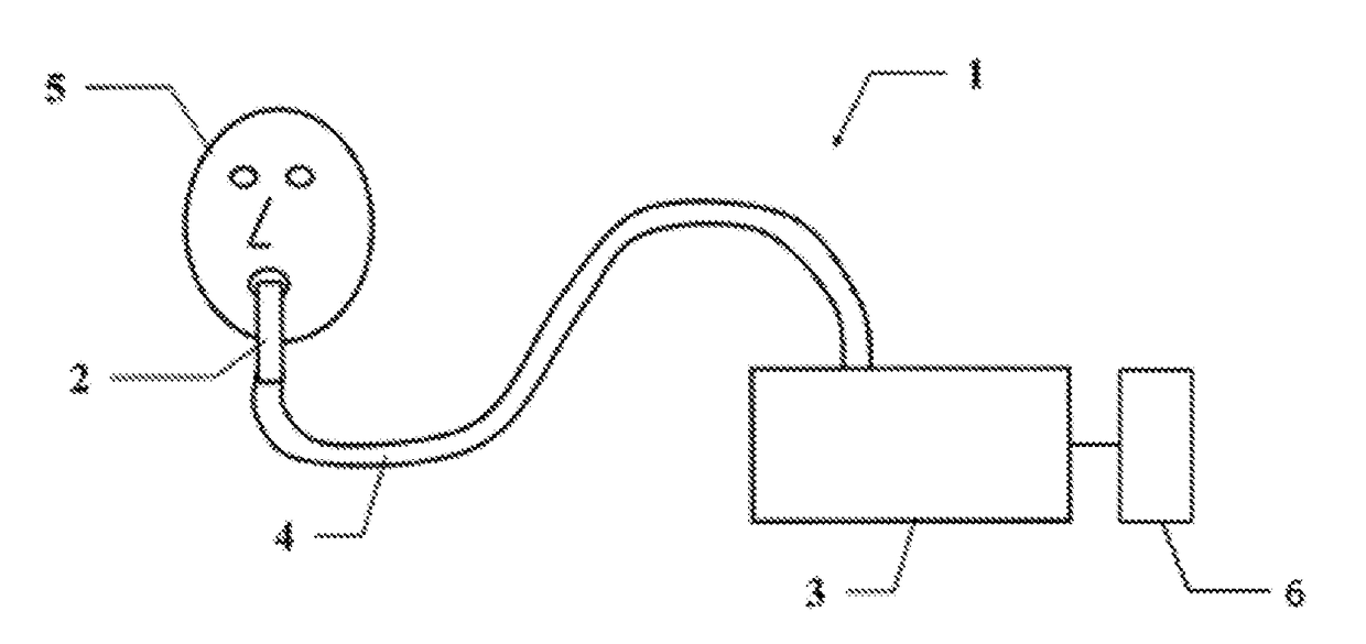
[0052]The present invention relates to a device (1) for stimulating the tracheobronchial air of a patient (5) suffering from an obstructive ventilatory disorder and able to modify the rheology of his tracheobronchial mucus.

[0053]For the purposes of the present invention, the expression “obstructive ventilatory disorders” includes the pathologies listed above, but also extends to disorders associated with nasal obstruction, such as sinusitis, which corresponds to sinus obstruction following inflammation of the mucous membranes of the nose resulting in altered drainage of the nasal mucus.

[0054]Now, and preferably, the device according to the invention will target the bronchial mucus and will therefore aim at stimulating of intra-pulmonary air.

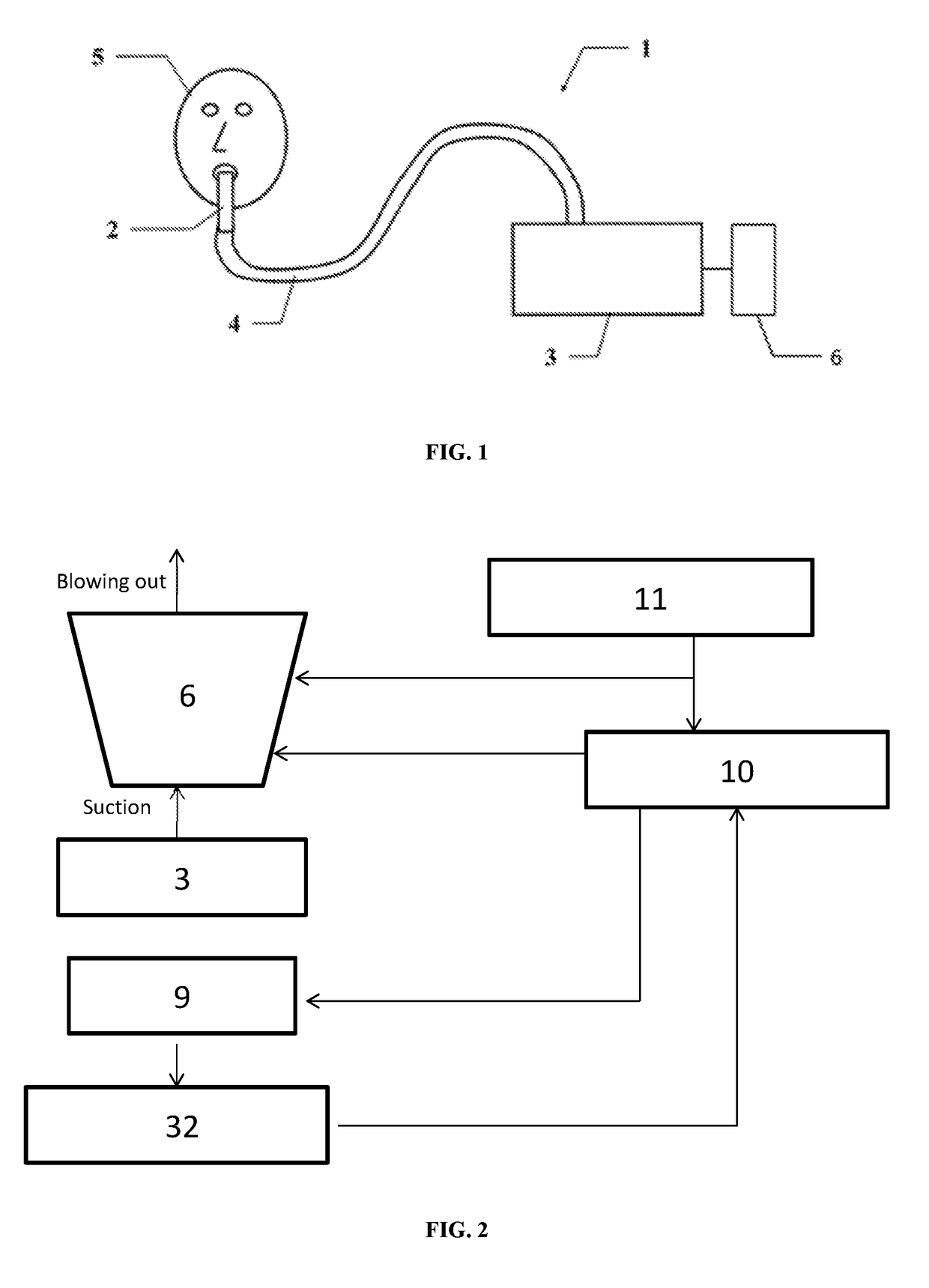
[0055]In some embodiments, the device includes a negative pressure generator (6) that includes a vacuum pump (7) with a flow rate greater than 20 L / min and a vacuum descent capacity of at least 200 mbar. Preferably, said vacuum pump (7) is a diap...


PUM


Abstract

Disclosed is a device for stimulating the tracheobronchial air of a patient suffering from an obstructive ventilatory disorder and able to modify the rheology of his tracheobronchial mucus, which includes a negative pressure generator, a physiological interface able to interface the device with the patient's respiratory apparatus, a connection pipe connecting the physiological interface to the negative pressure generator, and a control circuit capable of controlling the negative pressure generator, during the passive expiration phase, for the application of a succession of alternation of negative pressure and venting impulses with a determined frequency and a duty cycle determined during a first part of an expiration cycle and then a second frequency and a second duty cycle during a second part of the expiration cycle and to reiterate a defined number of expiration cycles.

Description

FIELD OF INVENTION[0001]The present invention pertains to the field of the treatment of obstructive ventilatory disorders. In particular, the invention relates to a device for stimulating mucus to improve its expectoration.BACKGROUND OF INVENTION[0002]In the healthy individual, the lungs are covered by a “film” called mucus, having a thickness of a few millimeters and a very fluid normal consistency. The function of this mucus is to protect the lung cells by isolating them from direct contact with air inspired by the lungs. The renewal of this mucus is ensured by cilia, mobile excrescences lying on the surface of the bronchi. These cilia, called vibratory cilia, beat towards the proximal part of the airways, eliminating the inhaled particles trapped in the gel phase of the mucus; said particles sliding on the layer of cilia, like on a conveyor belt. The clearance (the capacity of a mucociliary tissue, organ or organism to eliminate a substance from a given fluid) is carried out at a...

Claims


Application Information

Patent Timeline
IPC IPC(8): A61M16/00A61M16/20G16H40/63
CPCA61M16/024A61M16/0051A61M16/0009A61M16/0003A61M16/202G16H40/63A61M2016/0027A61M2205/6054A61M2205/505A61M16/0006G16H40/60G16H20/40
Inventor LANTZ, JEAN-SEBASTIENMITHALAL, ADRIEN
Owner PHYSIO ASSIST
Why Eureka
Try Eureka