Reduced power consumption for llc resonant converter under light load

Active Publication Date: 2022-08-11
EXCELSYS TECH LTD
View PDF6 Cites 0 Cited by
  • Summary
  • Abstract
  • Description
  • Claims
  • Application Information

AI Technical Summary

Benefits of technology

[0005]It is therefore an object to provide an improved LLC resonant converter having low output under no- or light-load conditions.
[0006]The following presents a simplified summary relating to one or more aspects and/or embodiments disclosed herein. As such, the following summary should not be considered an extensive overview relating to all contemplated aspects and/or embodiments, nor should the following summary be regarded to identify key or critical elements relating to all contemplated aspects and/or embodiments or to delineate the scope associated with any particular aspect and/or embodiment. Accordingly, the following summary has the sole purpose to present certain concepts relating to one or more aspects and/or embodiments relating to the mechanisms disclosed herein in a simplified form to precede the detailed description presented below.
[0007]One aspect of the disclosure describes a method of operating a series resonant LLC converter coupled via one or more transformers on an AC output bus to one or more output modules whose outputs are coupled to a load. The method can include delivering power to the AC output bus via a first switching section converting power from a high voltage input, the AC output bus configured to inductively deliver power to the one or more output modules. The method can also include monitoring current in an LLC resonant tank coupled to the AC output bus, and when the current drops below a light- or no-load threshold, then switching the first switching section off, and delivering power to the AC output bus via a second switching section receiving power at a lower voltage than the high

Problems solved by technology

However, it may not be possible to completely turn off the LLC resonant converter by increasing the switching frequency because as the switching frequency gets significantly higher than the resonant frequency, parasitic effects become important.
Such parasitic effects may become particularly significant when there is no load on the converter.
That is, even when the load on the converter has been removed and it would be desirable to turn the converter off, the converter may continue to produce high output voltages and/or high input power due to high-frequency parasiti

Method used


Image

  • Reduced power consumption for llc resonant converter under light load
  • Reduced power consumption for llc resonant converter under light load
  • Reduced power consumption for llc resonant converter under light load

Examples


first embodiment

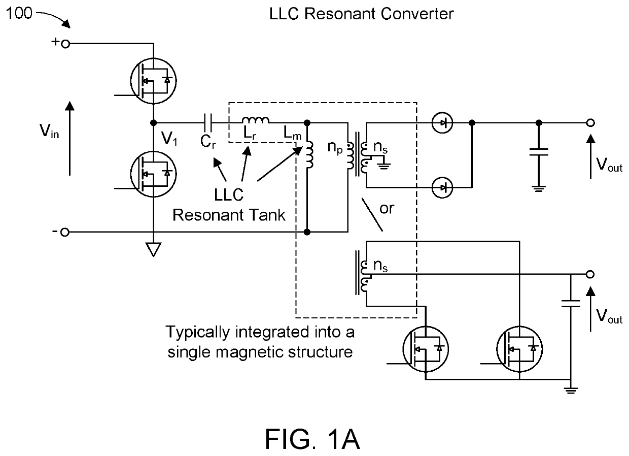
[0052]FIG. 1A depicts illustrates an LLC resonant converter topology that uses half-bridge switching. LLC resonant converter unit 100 includes a switching section with two switches (e.g., forming a half bridge) and an LLC tank that includes a capacitor, Cr, and two inductors, Lr and Lm, arranged as shown. The LLC tank may be associated with a resonant frequency that is a function of its impedance value. Accordingly, the LLC tank may also be referred to as a resonant tank. The switches may be implemented using transistors, such as FET transistors, and may be used to convert input voltage Vin to V1 by turning the transistors on or off (e.g., by applying appropriate voltages to the gates of the transistors). The input voltage, Vin, may be a DC voltage and the voltage signal, V1, may be a square wave, for example. The voltage signal, V1, generated by the switches may be provided to the LLC tank.

[0053]LLC resonant converter unit 100 includes two output modules each driven by a single pri...

second embodiment

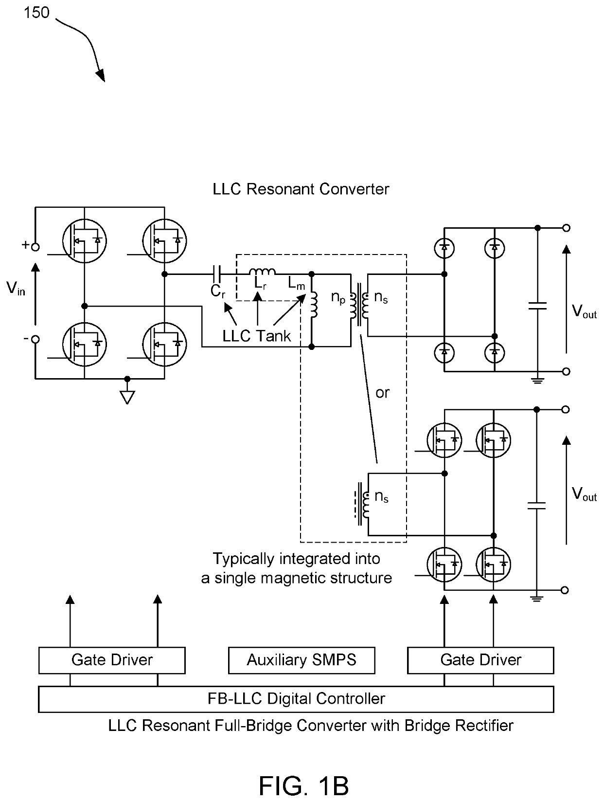
[0055]FIG. 1B depicts an LLC resonant converter topology that uses full-bridge switching. LLC resonant converter unit 150 includes a switching section with four switches (e.g., forming a full bridge) and an LLC resonant tank that includes a capacitor, Cr and two inductors, Lr, Lm arranged as shown. Full-bridge switching may provide similar functionality as half-bridge switching, at a cost of additional switches and more winding coils. Full-bridge switching may use half of the current used by a half-bridge topology, however, and may therefore be preferable when conduction losses are likely to be significant.

[0056]The embodiments disclosed herein are often shown in half-bridge configurations, but those of skill in the art can apply either the half-bridge or full-bridge topologies in FIGS. 1A and 1B to the embodiments disclosed herein.

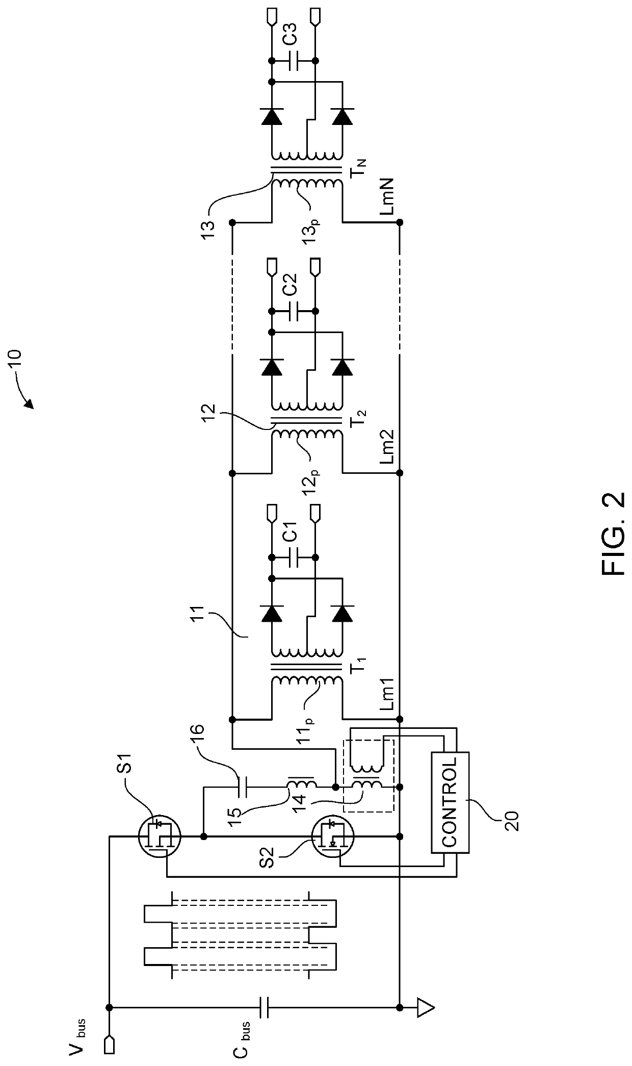
[0057]FIG. 2 illustrates a schematic of one embodiment of a known LLC resonant converter 10 with a parallel inductive element. LLC resonant converter 10 ...


PUM


Abstract

This disclosure provides a resonant LLC power converter unit to provide a plurality of power outputs. The power converter unit includes multiple transformers arranged such that at least one primary winding of each transformer is connected in parallel and configured to provide a power output to a secondary that powers one of the plurality of outputs. One of these transformers, or a parallel choke across an output bus, can be used to provide lower power to the output bus during a standby state (i.e., during a light- or no-load condition). The power converter unit includes a first switching section for providing a first power input during normal operation and a second switching section for providing a second power input during no- or light-load conditions.

Description

FIELD OF THE DISCLOSURE[0001]The disclosure relates to LLC resonant converters. In particular, the disclosure relates to an LLC resonant converter for improving a no-load state operation.DESCRIPTION OF RELATED ART[0002]LLC resonant converters are power supply devices that convert a DC input into an AC output. Such converters include switches coupled between a DC voltage input and an LC section that generally includes one or more inductors (L) and capacitors (C). The switches, which may be implemented using MOSFET transistors, are switched on and off at a particular switching frequency to generate a square wave that is provided as an input to the LC section (which may be referred to as an “LLC tank”). The LLC tank filters the input square wave and generates a sinusoidal output current, which is in turn provided to the primary windings of one or more transformers.[0003]The transformers may be used for voltage scaling and signal isolation, and may produce an output signal that is provi...

Claims


Application Information

Patent Timeline
IPC IPC(8): H02M3/335H02M1/00H02M1/08
CPCH02M3/33571H02M3/33573H02M1/0058H02M1/0009H02M1/083H02M3/33592H02M1/0032H02M1/0048H02M3/01H02M1/0095H02M1/0067H02M3/335Y02B70/10H02M3/33569H02M7/4815
Inventor MORRISON, RICHARDGASILOVS, ANDREJSBRADLEY, PHELIM SEAMUS
Owner EXCELSYS TECH LTD
Why Eureka
Try Eureka