Cutting a workpiece

Active Publication Date: 2019-08-15
TRUMPF WERKZEUGMASCHINEN GMBH & CO KG
View PDF0 Cites 1 Cited by
  • Summary
  • Abstract
  • Description
  • Claims
  • Application Information

AI Technical Summary

Benefits of technology

[0048]In the simplest case, the detector can be a photodiode that records or measures the intensity of the radiation reflected from the workpiece, typically process radiation, thermal radiation and/or reflected or scattered machining radiation, in particular laser radiation, generated during the interaction of the machining beam with the workpiece. The detector, e.g. in the form of a photodiode, can for example be arranged in the beam source for generating the machining beam, for example a solid-state laser for generating a laser beam. In particular, detecting laser radiation reflected from the workpiece has proven advantageous since in this case the machining beam can be irradiated at a power that is considerably lower than the detection of the process luminescence or thermal radiation, meaning that the cut-free part is not damaged during the check. The latter case is advantageous in particular if the cut-free part is a useful part.
[0049]In one embodiment, the machine comprises a beam source and the control device is designed or programmed to control the beam source to increase the power of the machining beam, in particular in steps, during irradiation of the check position. As described above in relation to the method, changing the power of the beam source can very quickly increase the intensity of the machining beam at the check position either continuously or in steps, and so the check duration need not be extended, or may only need extending slightly, compared with a check using a constant power.
[0050]In a further embodiment, the control device is designed to control the beam source to irradiate the check position with the machining beam in a pulsed manner and

Problems solved by technology

Machine elements, in particular carried-along machine elements, can be damaged by slugs or useful parts located in part beneath the workpiece plane.
The workpiece can also be moved or raised accidentally due to an interlocking fit, such that the contour precision is no longer pr

Method used


Image

  • Cutting a workpiece
  • Cutting a workpiece
  • Cutting a workpiece

Examples


Embodiment Construction

[0062]In the following description of the drawings, identical reference numerals are used for the same components or those having the same function.

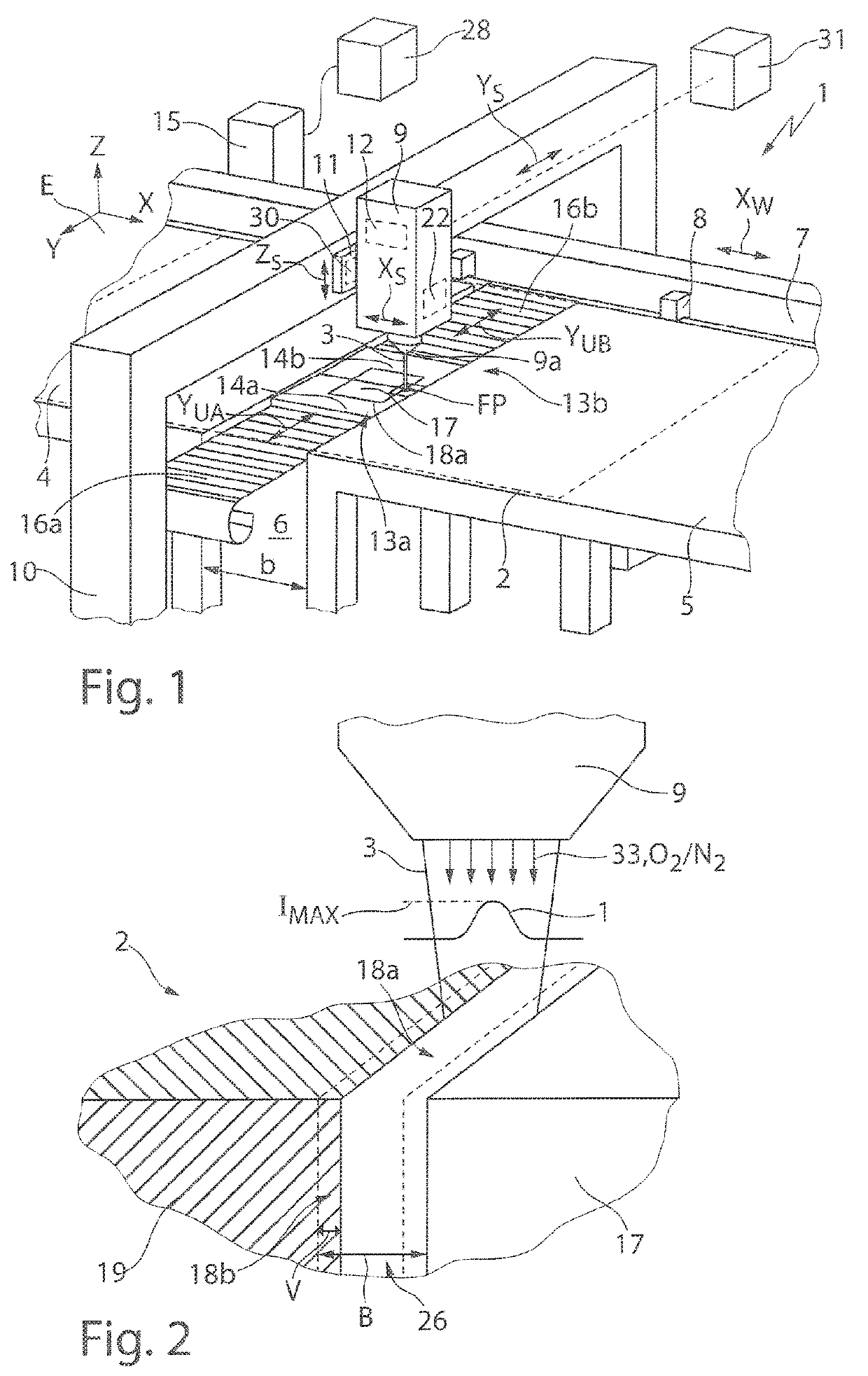
[0063]FIG. 1 shows an example design of a machine 1 for laser-machining, more specifically laser-cutting, a plate-shaped workpiece 2 (shown in dashed lines) by means of a laser beam 3. To cut the workpiece 2, another type of thermal machining beam can also be used instead of a laser beam 3. During the machining, the workpiece 2 rests on two workpiece bearing surfaces 4, 5, which in the example shown form the top faces of two workpiece tables and define a bearing plane E (X-Y plane of an XYZ coordinate system) for bearing the workpiece 2.

[0064]By means of a conventional movement and retaining device 7, comprising a drive and clamping devices 8 in the form of clamping claws for holding the workpiece 2 in place, the workpiece 2 can be shifted on the workpiece bearing surfaces 4, 5 in a first movement direction X (hereinafter: X-direction) i...


PUM

PropertyMeasurementUnit
Fractionaaaaaaaaaa
Fractionaaaaaaaaaa
Poweraaaaaaaaaa

Abstract

A method for cutting a workpiece includes cutting the workpiece along a predefined cutting contour to separate a workpiece part from a scrap part, and checking whether the workpiece part has been fully separated from the scrap part during the cutting. The workpiece is re-cut along an additional cutting contour laterally offset from the predefined cutting contour if it is found during the checking that the workpiece part has not been fully separated from the scrap part. The disclosure also relates to an associated machine for cutting a workpiece.

Description

CROSS REFERENCE TO RELATED APPLICATIONS[0001]This application is a continuation of and claims priority under 35 U.S.C. § 120 from PCT Application No. PCT / EP2017 / 076426, filed on Oct. 17, 2017, which claims priority from German Application No. 10 2016 220 459.9, filed on Oct. 19, 2016. The entire contents of each of these priority applications are incorporated herein by reference.TECHNICAL FIELD[0002]The present invention relates to a method for cutting a plate-like workpiece, for example, a metal sheet.BACKGROUND[0003]Plate-like workpieces, e.g. metal sheets, can be cut by means of thermal or by means of mechanical machining. In thermal machining by means of a machining beam, for example by means of a laser beam, a workpiece part is fully separated from a scrap part along a cutting contour. The scrap part may be a scrap workpiece or a scrap skeleton of the workpiece from which the workpiece part (useful part) is cut free. Alternatively, the cut-free part may be a scrap part (waste),...

Claims


Application Information

Patent Timeline
IPC IPC(8): B23K26/38B23K26/142B23K26/0622
CPCB23K26/38B23K26/142B23K26/0622B23K26/03G01N21/88B23K26/032B26F1/3813B26F1/38G01N21/8851B23K26/126B26F1/00
Inventor MIENHARDT, UWESPIESS, MARTINSCHOENHARDT, GUIDOKRUTZKE, MICHAELWOLF, DENNISKRENZ, CARSTEN
Owner TRUMPF WERKZEUGMASCHINEN GMBH & CO KG
Why Eureka
Try Eureka