Regenerative braking control apparatus for electrically driven vehicle

a technology of electrically driven vehicles and control apparatuses, which is applied in the direction of brake systems, failure to meet safety requirements, electric devices, etc., can solve the problems of negative influence on the drivability of the vehicle, and achieve the effects of improving the travel stability of the electrically driven vehicle, reducing the load on the electric motor and the associated peripheral devices, and improving convenience for the driver

Active Publication Date: 2018-07-19
MITSUBISHI MOTORS CORP
View PDF0 Cites 6 Cited by
  • Summary
  • Abstract
  • Description
  • Claims
  • Application Information

AI Technical Summary

Benefits of technology

[0021]According to the invention of claim 1, when a situation happens in which the selected braking force, i.e., the regenerative braking force selected by the driver, is determined to be unacceptable, the driver is notified of that situation. This enables the driver to recognize that the regenerative braking force to be actually generated may not be equal to the selected braking force, which may advantageously improve convenience for the driver. More specifically, by virtue of such notification, the driver can drive the vehicle with recognition that the regenerative braking force to be actually generated may be smaller than the selected braking force, so that he/she is induced to drive the vehicle while keeping in mind the necessities of relatively early braking and/or relatively wide distance from the preceding vehicle. In addition, by virtue of the above, the driver may be suggested to reselect the braking force so as to change the selected braking force into a lower one.
[0022]According to the invention of claim 2, Output-Requested-Torque value for the electric motor is set to be a torque value smaller than the selected braking force in a case where the selected braking force is determined to be unacceptable. By virtue of this, the loads imposed on the electric motor and the associated peripheral devices may be reduced. Also, this may advantageously improve the travel stability of the electrically driven vehicle.
[0023]According to the invent

Problems solved by technology

Too high a regenerative braking force, however, may result in too rapid decelerat

Method used


Image

  • Regenerative braking control apparatus for electrically driven vehicle
  • Regenerative braking control apparatus for electrically driven vehicle
  • Regenerative braking control apparatus for electrically driven vehicle

Examples


Embodiment Construction

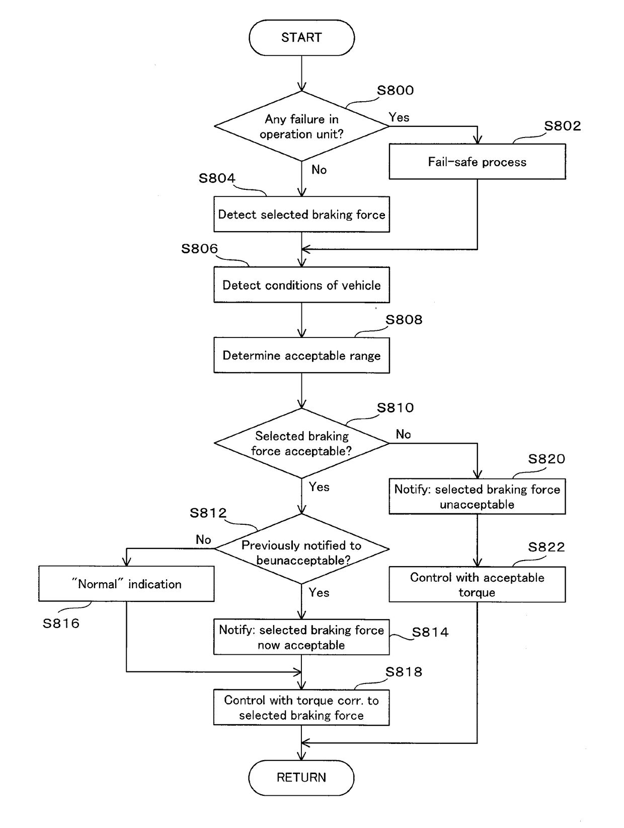
[0037]With reference now to the accompanying drawings, a preferred embodiment of a regenerative braking control apparatus 10 according to the present invention will be described in detail.

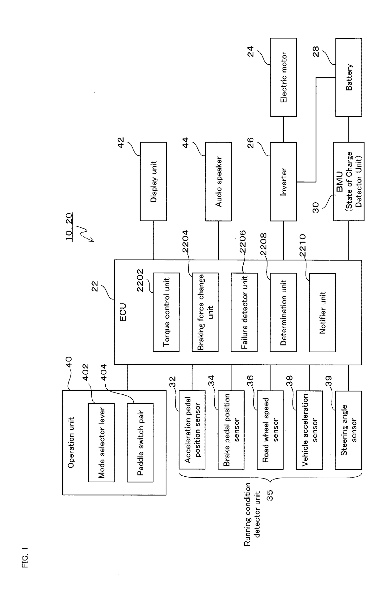
[0038]FIG. 1 is a schematic illustration showing a structure of a regenerative braking control apparatus 10 according to an embodiment of the present invention. With this embodiment, the regenerative braking control apparatus 10 is equipped on an electric vehicle (EV) having an electric motor 24 as the only drive power source of the vehicle.

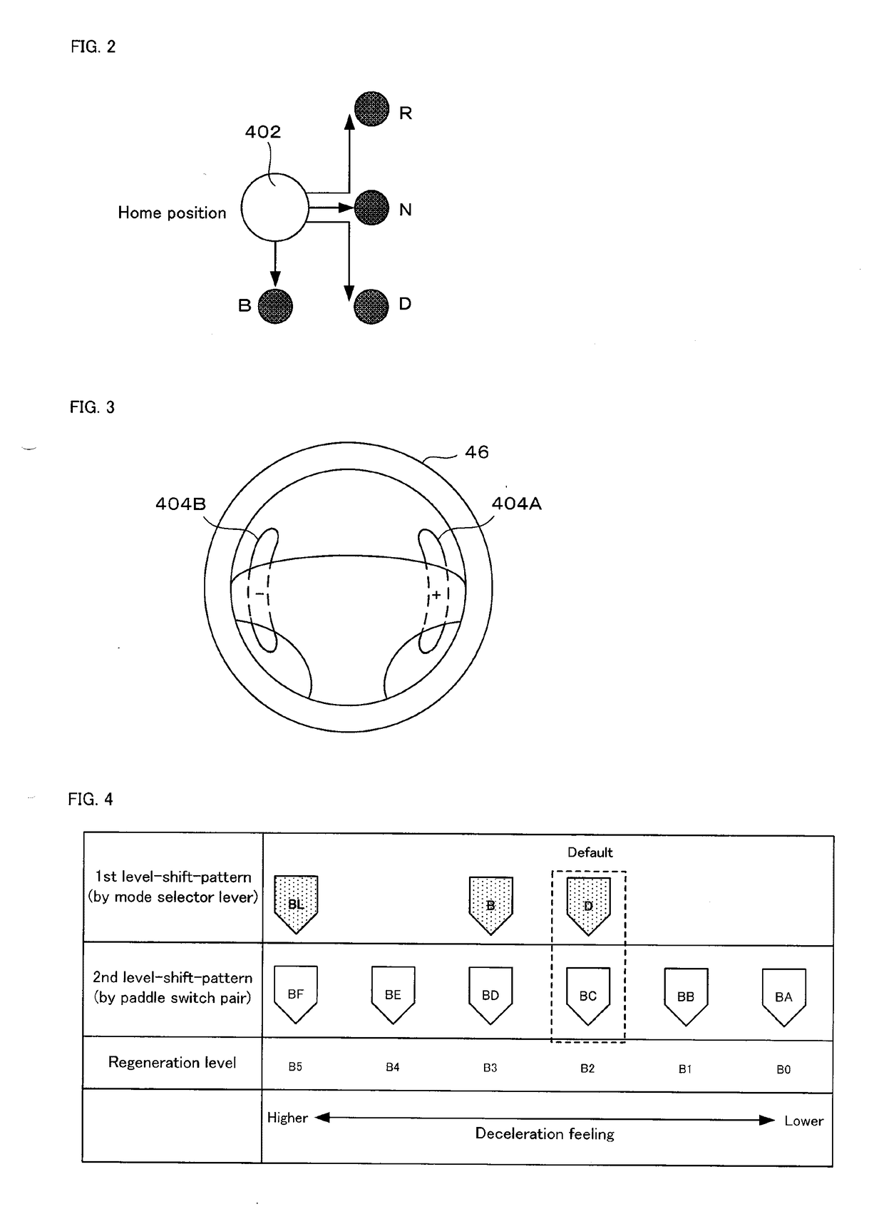
[0039]The regenerative braking control apparatus 10 includes a vehicle electronic control unit (vehicle-ECU) 22, an electric motor 24 (serving as a drive motor generator), an inverter 26, a battery 28, a battery management unit (BMU) 30, an accelerator pedal position sensor 32, a brake pedal position sensor 34, a road wheel speed sensor 36, a vehicle acceleration sensor 38, a steering angle sensor 39, an operation unit 40 (including a mode selector lever 402 and...


PUM


Abstract

A regenerative braking control apparatus equipped on an electrically driven vehicle having road wheels and an electric motor for driving the road wheels for running. An operation unit is provided for the driver of the vehicle to select a magnitude of the braking force to be generated by the electric motor during regenerative braking. A determination unit determines, on the basis of conditions of the electrically driven vehicle, whether or not a selected braking force selected through the operation unit is acceptable. A notifier unit is constructed such that, in a case where the selected braking force is determined to be unacceptable by the determination unit, the notifier unit provides a corresponding notification to the driver.

Description

TECHNICAL FIELD[0001]The present invention relates to a regenerative braking control apparatus for an electrically driven vehicle having road wheels and an electric motor for driving the road wheels for running.BACKGROUND OF THE INVENTION[0002]From prior art, there have been known electrically driven vehicles having an electric motor, which is powered by electric energy charged in a battery in order to serve as a drive power source. Such electrically driven vehicles include so-called electric vehicles (EVs) having an electric motor as the only drive power source, as well as so-called hybrid electric vehicles (HEVs) having an electric motor and an internal combustion engine as the drive power sources.[0003]Many electrically driven vehicles have a regenerative braking system, in which the electric motor is used as an electric generator, which is driven to provide braking force (regenerative braking force) so as to decelerate the vehicle, while the kinetic energy of the vehicle is conv...

Claims


Application Information

Patent Timeline
IPC IPC(8): B60L7/18B60T7/08B60T7/12B60T8/172B60T17/22B60L15/20B60L3/00B60L11/18
CPCB60L7/18B60T7/085B60T7/12B60T8/172B60T17/221B60L15/2009B60L3/0061B60L3/0076B60L11/1861B60T2210/12B60T2270/60B60T2270/40B60L2250/10B60L2250/16B60L2240/423B60L2240/54B60T1/10B60T7/22B60T2270/402B60T2270/604B60L58/15F16D61/00Y02T10/64Y02T10/70Y02T10/72B60L58/12
Inventor SHIMIZU, RYOHANDA, KAZUNORIIKOMA, NORIHIKOTOMITA, YOSHINORI
Owner MITSUBISHI MOTORS CORP
Why Eureka
Try Eureka