Exhaust gas control apparatus for internal combustion engine and exhaust gas control method for internal combustion engine

a technology of exhaust gas control apparatus and internal combustion engine, which is applied in the direction of exhaust treatment electric control, electrical control, machines/engines, etc., can solve the problems of limited oxygen supply to the filter, reducing the output of the internal combustion engine, and not regenerating the filter, so as to achieve the effect of efficient suppression of thermal deterioration of the catalys

Inactive Publication Date: 2018-07-19
TOYOTA JIDOSHA KK
View PDF0 Cites 14 Cited by
  • Summary
  • Abstract
  • Description
  • Claims
  • Application Information

AI Technical Summary

Benefits of technology

[0006]There is a case where the filter needs to be regenerated when the internal combustion engine is started under cold conditions. However, when the internal combustion engine is started under cold conditions, since the temperature of the filter is comparatively low, even in a case where the oxygen concentration of exhaust gas flowing into the filter is sufficiently high, the filter is not regenerated until the temperature of the filter becomes sufficiently high. In a case where the timing until the filter is regenerated is long, for example, the output of the internal combustion engine may be lowered due to the occurrence of clogging of the filter. Accordingly, it is desirable to quickly increase the temperature of the filter.

Problems solved by technology

For this reason, oxygen is limitedly supplied to the filter in a case where the internal combustion engine is operated at an air-fuel ratio greater than the stoichiometric air-fuel ratio, in a case where a fuel cut is performed due to deceleration, or the like.
However, when the internal combustion engine is started under cold conditions, since the temperature of the filter is comparatively low, even in a case where the oxygen concentration of exhaust gas flowing into the filter is sufficiently high, the filter is not regenerated until the temperature of the filter becomes sufficiently high.
In a case where the timing until the filter is regenerated is long, for example, the output of the internal combustion engine may be lowered due to the occurrence of clogging of the filter.
However, the temperature of the catalyst further increases during regeneration of the filter, the filter is overheated, and there is a possibility that the catalyst is thermally deteriorated.
When the first control is executed, since heat of exhaust gas is consumed in the first catalyst, an increase in the temperature of the filter provided downstream of the first catalyst becomes slow.
However, since heat is discharged outside the exhaust passage in the exhaust passage from the first catalyst to the second catalyst, a large amount of unburned fuel is needed in order to increase the temperature of the second catalyst, and a lot of time is needed to increase the temperature of the second catalyst.
In a case where heat is generated in the first catalyst so as to regenerate the filter, there is a possibility that the temperature of the first catalyst becomes excessively higher than normal and the first catalyst is thermally deteriorated.
Furthermore, since unburned fuel flows out from the first catalyst, the amount of unburned fuel oxidized with the first catalyst decreases to that extent.

Method used


Image

  • Exhaust gas control apparatus for internal combustion engine and exhaust gas control method for internal combustion engine
  • Exhaust gas control apparatus for internal combustion engine and exhaust gas control method for internal combustion engine
  • Exhaust gas control apparatus for internal combustion engine and exhaust gas control method for internal combustion engine

Examples


example

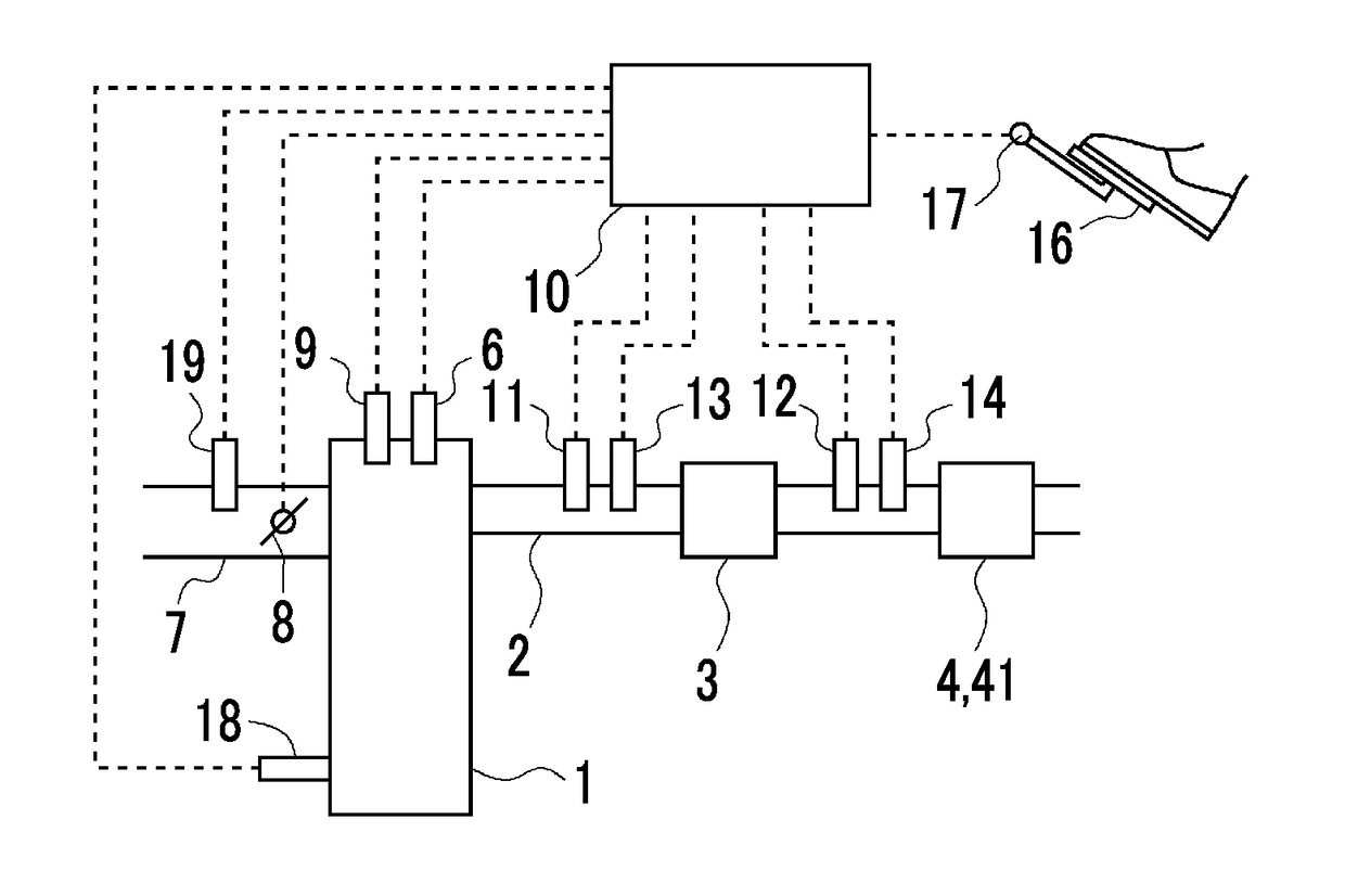
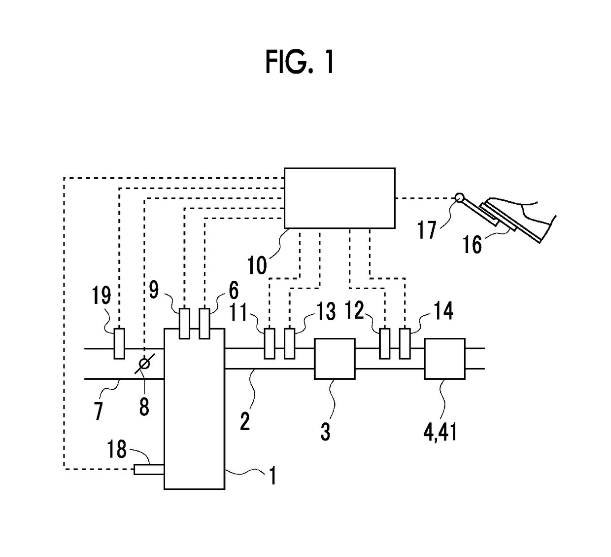
[0026]FIG. 1 is a diagram showing the schematic configuration of an internal combustion engine 1 according to the example and an intake system and an exhaust system of the internal combustion engine. The internal combustion engine 1 shown in FIG. 1 is a gasoline engine. The internal combustion engine 1 is mounted in, for example, a vehicle. An exhaust passage 2 is connected to the internal combustion engine 1. In the middle of the exhaust passage 2, a first catalyst 3 as a three-way catalyst and a filter 41 that supports a second catalyst 4 as a three-way catalyst are provided in order from an upstream side.

[0027]The first catalyst 3 and the second catalyst 4 have an oxygen storage ability. That is, the first catalyst 3 stores oxygen when an air-fuel ratio of exhaust gas is greater than a stoichiometric air-fuel ratio, and discharges oxygen when the air-fuel ratio of exhaust gas is smaller than the stoichiometric air-fuel ratio. The first catalyst 3 and the second catalyst 4 have an...


PUM


Abstract

An exhaust gas control apparatus includes a first catalyst, a filter, and an electronic control unit. The electronic control unit is configured to alternately execute lean control and rich control multiple times. The lean control is control for, over a period longer than a period from when a target air-fuel ratio is set to a predetermined lean air-fuel ratio until an air-fuel ratio of exhaust gas flowing out from the first catalyst becomes greater than the stoichiometric air-fuel ratio, setting the target air-fuel ratio to the predetermined lean air-fuel ratio. The rich control is control for, over a period longer than a period from when the target air-fuel ratio is set to a predetermined rich air-fuel ratio until the air-fuel ratio of exhaust gas flowing out from the first catalyst becomes smaller than the stoichiometric air-fuel ratio, setting the target air-fuel ratio to the predetermined rich air-fuel ratio.

Description

CROSS-REFERENCE TO RELATED APPLICATIONS[0001]This application claims priority to Japanese Patent Application No. 2017-004113 filed on Jan. 13, 2017, incorporated herein by reference in its entirety.BACKGROUND1. Technical Field[0002]The present disclosure relates to an exhaust gas control apparatus for an internal combustion engine and an exhaust gas control method for an internal combustion engine.2. Description of Related Art[0003]A filter that traps particulate matter (hereinafter, referred to as PM) in exhaust gas is provided in an exhaust passage of an internal combustion engine. In a case where a PM amount (hereinafter, referred to as a PM deposition amount) trapped in the filter reaches a given amount, processing for eliminating the PM through oxidation is executed. The above-described processing is referred to as filter regeneration. In order that the PM trapped in the filter is oxidized, a temperature of the filter needs to be equal to or higher than a predetermined temperat...

Claims


Application Information

Patent Timeline
Patent Type & Authority Applications(United States)
IPC IPC(8): F01N3/023F01N3/08F02D41/22F02D41/02F02D45/00F02D13/02
CPCF01N3/0238F01N3/0814F02D41/222F02D41/0235F02D45/00F02D13/0211F02D41/3023F02D41/402F02D2041/0265F01N3/023F01N3/20F01N9/002F01N2250/02F01N3/0864F01N3/103F01N3/2033F01N3/0253F01N3/035F01N2430/06F01N2550/04F01N2560/025F01N2560/06F01N2610/03F01N2610/146F01N2900/0411F01N2900/0422F01N2900/08F01N2900/1402F01N2900/1404F01N2900/1602F01N2900/1606F01N2900/1812F01N2900/1821F01N13/009F02D41/0255F02D41/0245F02D41/025F02D41/029F02D41/064F02D41/1454F02D2200/0802F02D41/1475Y02T10/12Y02T10/40
Inventor KANEKO, NAOYAOHTSUKA, TAKAYUKI
Owner TOYOTA JIDOSHA KK
Why Eureka
Try Eureka