
EUV Reticle Pod

a technology of reticle pods and euv, which is applied in the field of reticle pods, can solve the problems of deteriorating the image quality projected onto the wafer, reticle pods still subject to particle contamination, and reticle pods still cannot provide sufficient protection for the reticl

Active Publication Date: 2018-07-26
GUDENG PRECISION IND CO LTD
View PDF13 Cites 17 Cited by
  • Summary
  • Abstract
  • Description
  • Claims
  • Application Information

AI Technical Summary

Benefits of technology

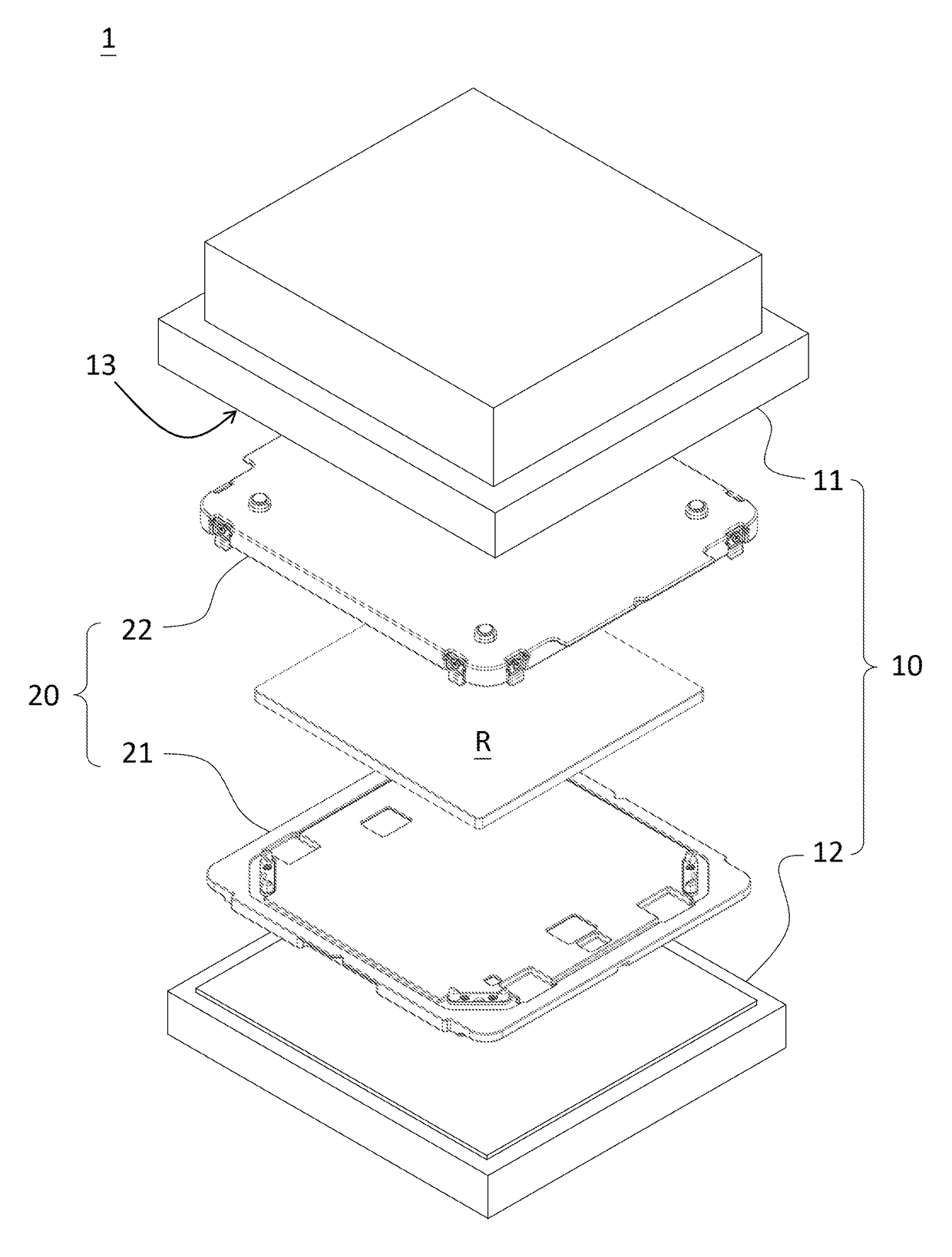
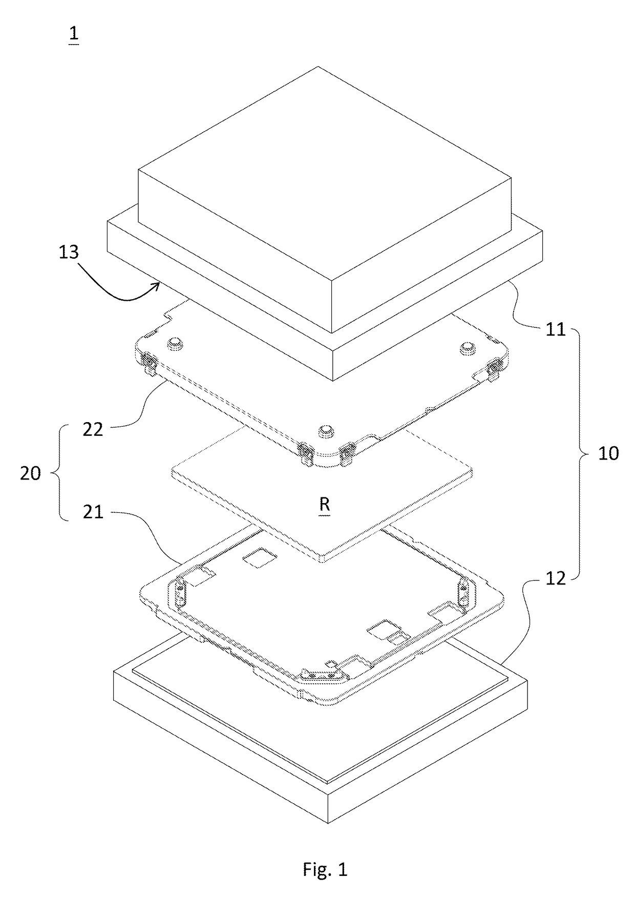
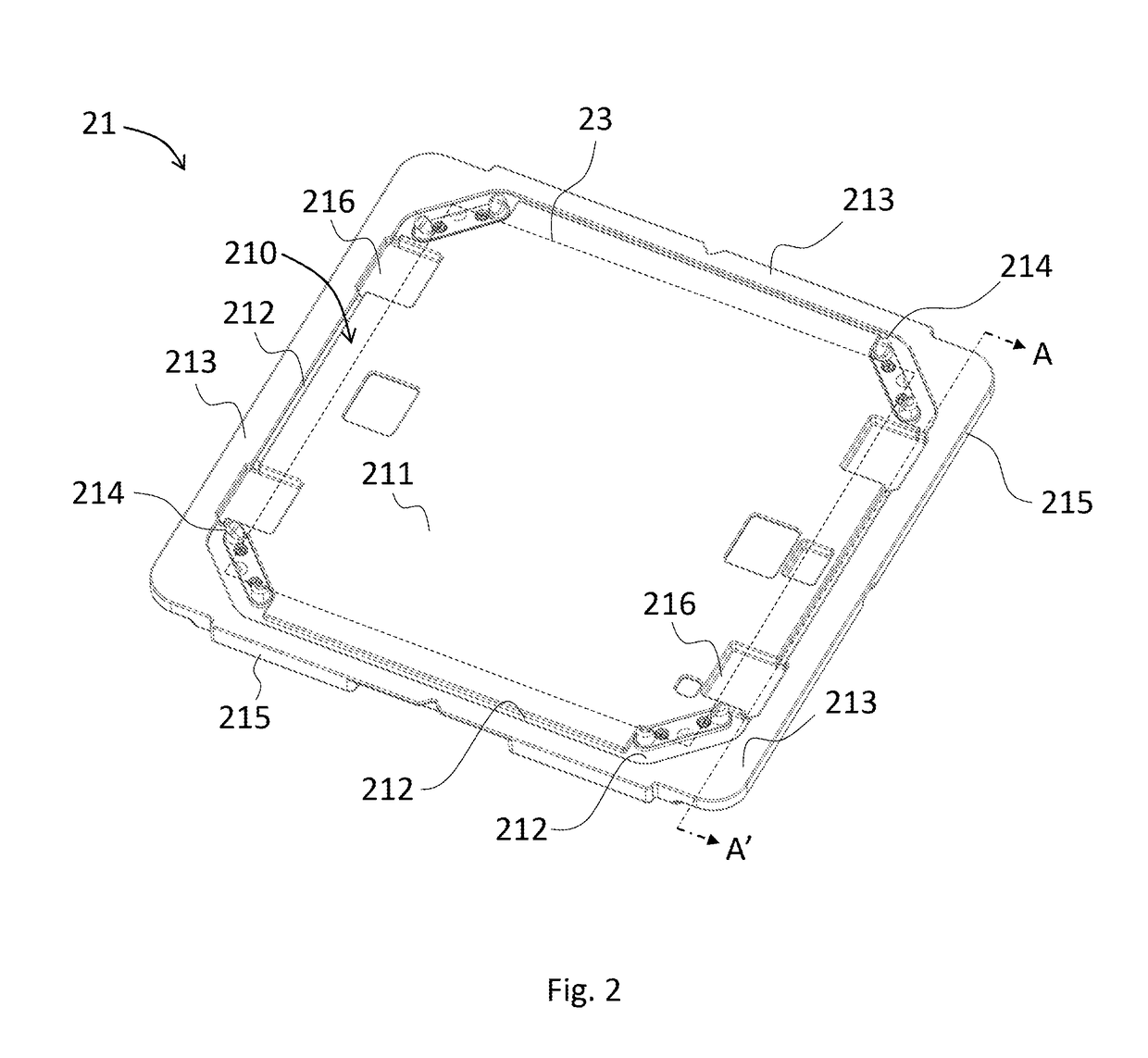
The present invention provides an EUV reticle pod with a carrying surface and an upper surface. The invention includes one or more circular-loop-structured trenches between the carrying surface and the upper surface. These trenches trap or capture particles to reduce particle contamination in the region between the carrying surface and the reticle during transportation. The invention improves the cleanliness of the reticle and prevents contamination during the manufacturing process.

Problems solved by technology

During the photolithography process, any particles attached on the wafer, such as dust or organic matters, would deteriorate the image quality projected onto the wafer.
However, even in a controlled environment, the reticle pods are still subjected to particle contamination resulting from the fluctuation of air pressure or the air disturbance by the movement of the container.
The particles can be carried into the region between the reticle and the container and even onto the reticle, so the reticle pods still couldn't provide sufficient protection to the reticle from particle contamination.

Method used


Image

  • EUV Reticle Pod
  • EUV Reticle Pod
  • EUV Reticle Pod

Examples


Embodiment Construction

[0028]The EUV reticle pod includes a base and a cover. At least one trench with circular loop structure is provide on the base to trap or capture particles. Therefore, the risk of particles migrating into the region between the carrying surface and the EUV reticle is mitigated. Reference will now be made in detail to elaborate the contents and the features of the embodiments of the present invention, examples of which are illustrated in the accompanying drawings. For clearly showing the features of the present invention, elements are simplified or omitted in the drawings, and the relative proportions of components are for exemplary purpose only.

[0029]Please refer to FIG. 1, which is an exploded view of an EUV reticle pod according to one embodiment of the invention. The EUV reticle pod 1 is used for containing an EUV reticle R. The EUV reticle pod 1 includes an outer box assembly 10 and an inner box assembly 20. The outer box assembly 10 includes an upper portion 11 and a lower port...


PUM

PropertyMeasurementUnit
widthaaaaaaaaaa
light permeableaaaaaaaaaa
sizeaaaaaaaaaa

Abstract

An EUV reticle pod is provided. The pod includes an inner and an outer box assembly. The inner box assembly contained in the outer box assembly includes a base and a cover. The base has an upper surface and a surrounding wall. The upper surface includes a carry surface, at least one trench, and a first contacting surface. The EUV reticle is carried above the carry surface. The trench has a circular loop structure and its bottom is lower than the carry surface. The carry surface, the trench, and the first contacting surface are sequentially distributed from the center of the upper surface towards the surrounding wall. The cover has a concave for accommodating the EUV reticle and a second contacting surface for cooperating with the first contacting surface to form an air-tight seal. The trench captures and traps particles to reduce the particle contamination on the reticle.

Description

RELATED APPLICATIONS[0001]This application claims priority to U.S. Provisional Patent Application No. 62 / 450,172, by Hsueh, et al., titled “Reticle Pod,” filed Jan. 25, 2017 which is hereby incorporated by reference herein in their entirely.BACKGROUND OF THE INVENTIONTechnical Field[0002]The present invention relates to a reticle pod. More particularly, the present invention relates to a dual containment EUV reticle pod.Description of Related Art[0003]In recent years, the semiconductor manufacturing technology advances rapidly, in which the photolithography process plays an important role. Generally, photolithography involves fabricating a light permeable reticle with desired pattern and projecting the pattern onto a wafer having photoresist by exposing to a light source. After etching and other process steps, the desired pattern is formed on the wafer.[0004]During the photolithography process, any particles attached on the wafer, such as dust or organic matters, would deteriorate t...

Claims


Application Information

Patent Timeline
Patent Type & Authority Applications(United States)
IPC IPC(8): G03F7/20H01L21/673G03F1/66
CPCG03F7/70741H01L21/67359G03F1/66H01L21/67353G03F7/2063G03F7/70033G03F7/70916
Inventor HSUEH, HSIN-MINCHUANG, CHIA-HOLEE, CHENG-JUHUANG, JENG-JIE
Owner GUDENG PRECISION IND CO LTD
Learn More