Joint assembly

a joint assembly and robot technology, applied in the direction of braking discs, manufacturing tools, gearing, etc., can solve the problem of fast response to critical failure needs

Active Publication Date: 2018-08-02
KASSOW ROBOTS APS
View PDF8 Cites 20 Cited by
  • Summary
  • Abstract
  • Description
  • Claims
  • Application Information

AI Technical Summary

Benefits of technology

[0007]It is an object of the present invention to wholly or partly overcome the above disadvantages...

Problems solved by technology

For instance, a robot configured to carry a load of e.g. 10 kilograms may in an unfortunate incident kill a worker standing nearby by dropping...

Method used


Image

  • Joint assembly
  • Joint assembly
  • Joint assembly

Examples


Embodiment Construction

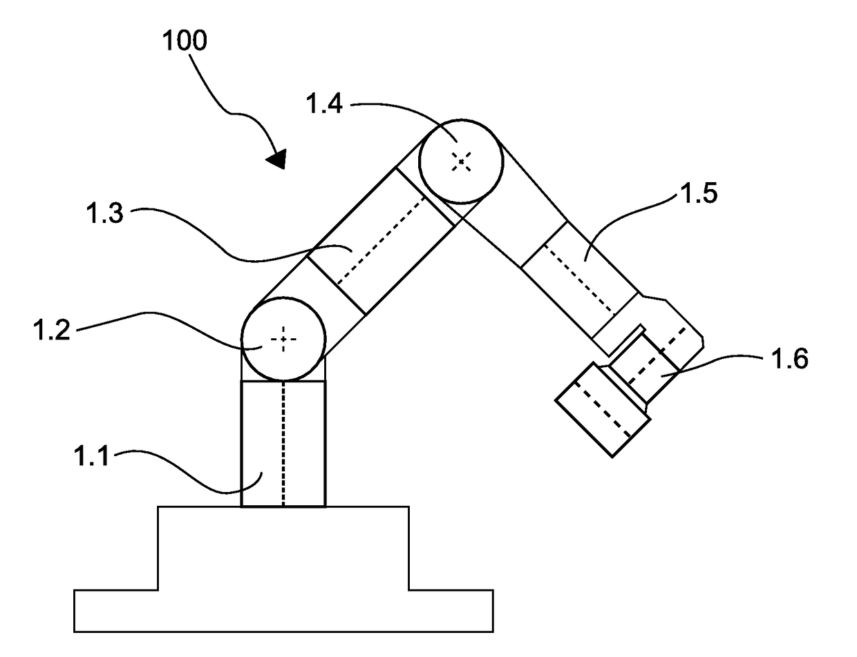
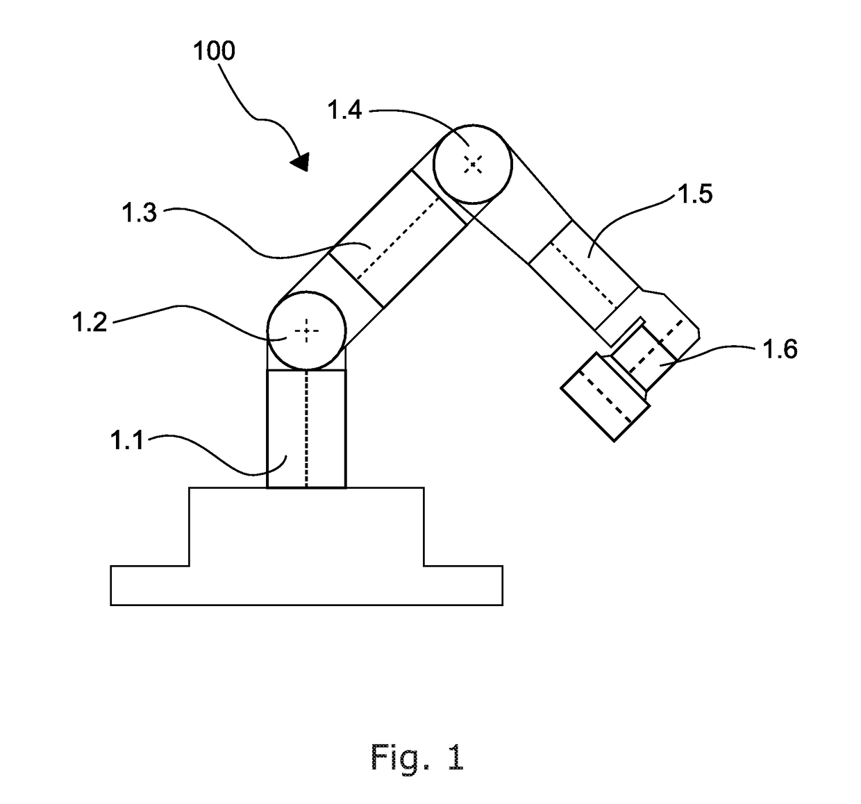
[0094]FIG. 1 shows a robotic arm having a number of joint assemblies 1. The joint assemblies 1.1, 1.3 and 1.5 are typically called rotational joints, and 1.2, 1.4 and 1.6 are typically called bending joints. However, despite their different orientations, the joint assemblies 1 generally have the same design. It will be understood that in particular, the joints may be longer in order to achieve a desired range for the entire arm 100. In the following, the term “output parts” refers to the parts that cannot rotate significantly relative to the gear box output, e.g. any component on FIG. 3 connected to output part 8. The term “house” refers to anything that cannot rotate significantly relative to the gear box housing, for instance any component on FIG. 3 connected to a housing 26. The term “rotor” refers to parts that cannot rotate significantly relative to the gear box input, for instance any component on FIG. 5 connected to rotor shaft.

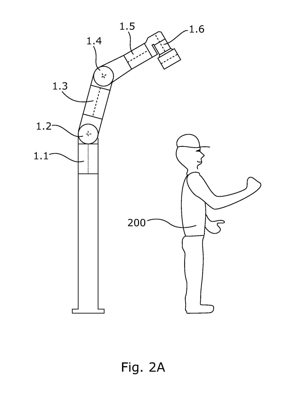
[0095]FIGS. 1, 2A and 2B show a robotic arm 100 ...


PUM


Abstract

The present invention relates to a joint assembly (1) for a robot (100), comprising a housing (26) connected with an output part (8), the housing comprising a housing wall (26A), a strain wave gearing system (90) comprising a wave generator (7), a flexspline (13), and a circular spline (36) connected to the output part (8), wherein the wave generator (7) is rotated by a rotor shaft (3), the rotor shaft being driven by an electric motor (140) comprising a stator (15) and a rotor magnet (16), the rotor magnet (16) being affixed to the rotor shaft (3), and wherein the joint assembly (1) further comprises a rotor brake (30) configured to stop/prevent relative movement between the rotor shaft (3) and the flexspline (13), and sensors arranged to measure the position of the housing (26) in relation to the output part (8). Furthermore, the present invention also relates to a robotic arm (100) comprising a joint assembly according to the present invention and to the use of the joint assembly according to the present invention.

Description

FIELD OF THE INVENTION[0001]The present invention relates to a joint assembly for a robot, to a robotic arm comprising a joint assembly according to the present invention and to the use of the joint assembly according to the present invention.BACKGROUND ART[0002]Joint assemblies are widely used in the robotic industry. Along with the extended use of robots in an increased number of situations, the requirements for the joint assemblies have changed. The joint assembly needs only to be configured in two variations, rotational joint assemblies and bending joint assemblies, in order to configure a robotic arm having six axes and hence being capable of being set to all frequently required positions.[0003]Today, it is commonly known to build robots from modular robot joint assemblies having a built-in electric circuit board in order to drive an electric motor. The electric motor may for instance comprise a stator and rotor / shaft with permanent magnets that drive a wave gear / harmonic drive...

Claims


Application Information

Patent Timeline
IPC IPC(8): B25J17/02B25J9/08B25J9/10B25J9/12B25J19/00B25J19/02F16H49/00F16D65/12F16D67/02
CPCB25J17/025B25J9/08B25J9/1025B25J9/126B25J19/0004B25J19/02F16H49/001F16D65/12F16D67/02Y10S901/29Y10S901/46Y10S901/23Y10S901/25Y10S901/20Y10S901/15F16D2121/16F16D2200/0026B25J17/0241
Inventor KASSOW, KRISTIAN
Owner KASSOW ROBOTS APS
Why Eureka
Try Eureka