Corrosive fluid heater, tank and manufacturing method

Active Publication Date: 2018-08-09
AKWEL SA
View PDF3 Cites 0 Cited by
  • Summary
  • Abstract
  • Description
  • Claims
  • Application Information

AI Technical Summary

Benefits of technology

[0017]Advantageously, the heat diffuser made of one of the anodized aluminum alloys or of anodized aluminum allows obtaining very good corrosion resistance performances in the aqueous urea solution.
[0018]According to one feature of the

Problems solved by technology

This solution is not yet adopted for light motor vehicles to the extent that the aqueous urea solution tank is located opposite the engine cooling system, which requires piping of considerable length traversing the entire vehicle and consequently cumbersome piping.
In addition, making stainless-steel plungers is expensive and complicated.
Plastic, generally thermoplastic, materials used for the overmolding have generally relatively low melt temperatures, which causes a limitation of the power density of the devi

Method used


Image

  • Corrosive fluid heater, tank and manufacturing method
  • Corrosive fluid heater, tank and manufacturing method
  • Corrosive fluid heater, tank and manufacturing method

Examples


Example

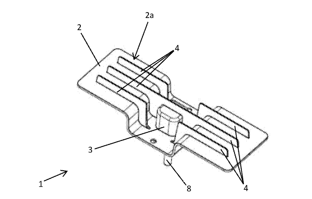
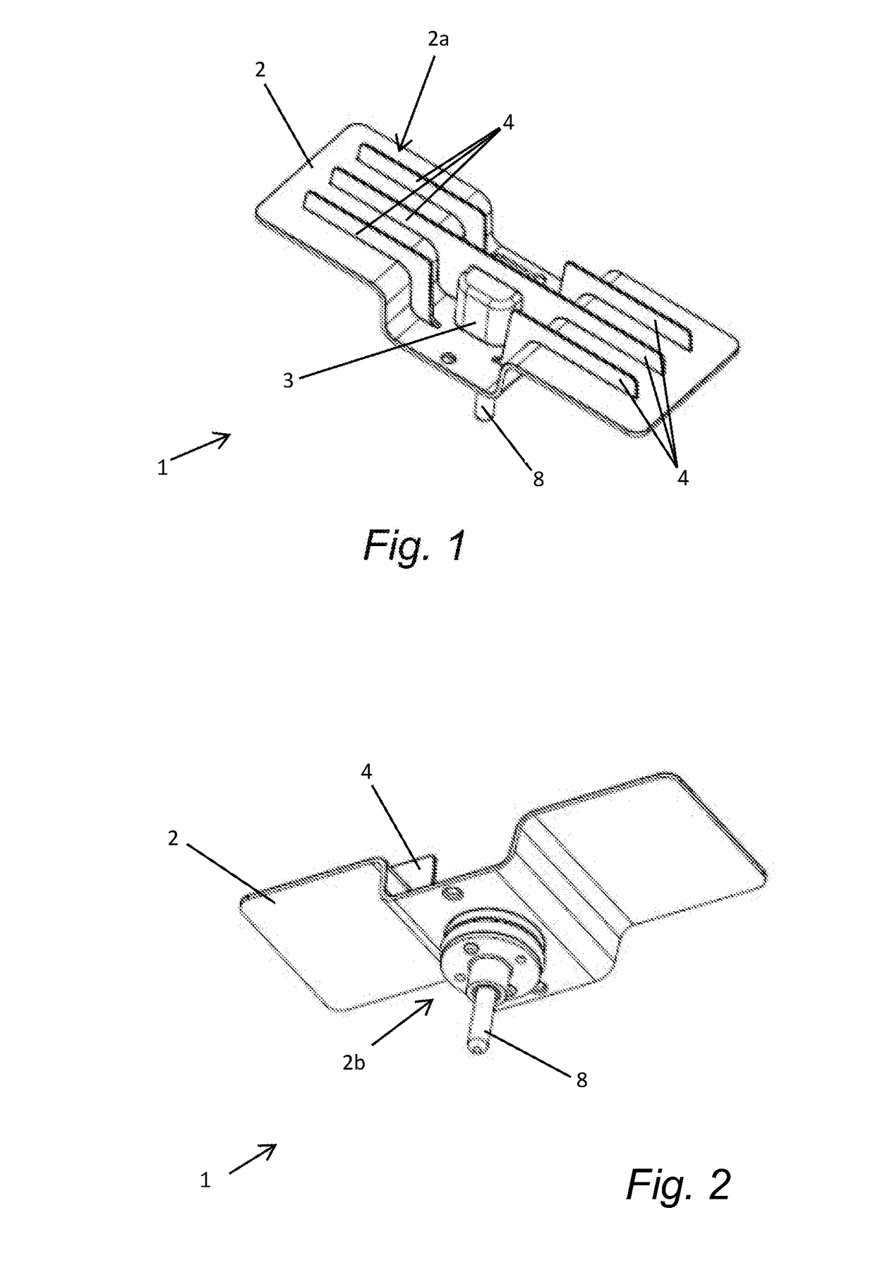
[0060]According to the invention and as illustrated in particular in FIG. 1, the aqueous urea solution heater 1 comprises a heat diffuser 2. The heat diffuser 2 comprises a first portion 2a intended to be immersed in an aqueous urea solution, and a second portion 2b non-anodized and intended to be arranged out of the aqueous urea solution, as represented in FIG. 6. The first portion 2a of the heat diffuser 2 is made of anodized aluminum or of anodized aluminum alloy and is configured to be in direct contact with the aqueous urea solution.

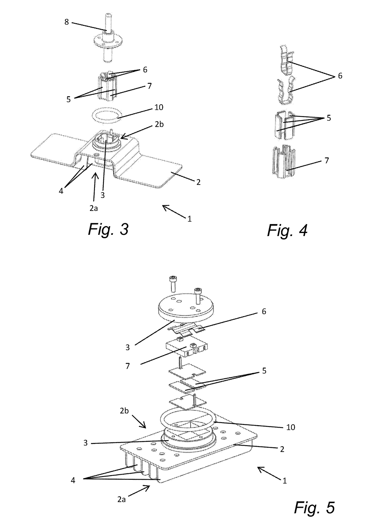
[0061]In addition, the heater 1 comprises a housing 3 configured to house at least one heating member 5. Of course, in one variant, the heater may comprise several housings each comprising one or more heating member(s) independent of each other or not.

[0062]In the example illustrated in FIG. 3 and in detail in FIG. 4, the heater comprises a plurality of heating members 5 grouped together in a support 7 and held in a housing 3 of the heater 1 by mean...


PUM

PropertyMeasurementUnit
Volumeaaaaaaaaaa

Abstract

The object of the invention is a heater of a corrosive fluid comprising at least one heat diffuser having at least a first portion intended to be immersed in a corrosive fluid, and at least a second portion intended to be arranged out of the corrosive fluid, at least one heating block comprising at least one heating member configured to heat the corrosive fluid, said heat diffuser comprising at least one housing in which the at least one heating block is housed at least partially, at least the first portion of the heat diffuser being made of anodized aluminum or of anodized aluminum alloy and is configured to be in direct contact with the corrosive fluid.
The object of the invention is also a corrosive fluid tank comprising a heater according to the invention and a method for manufacturing a heat diffuser of the heater according to the invention.

Description

TECHNICAL FIELD OF THE INVENTION[0001]The present invention concerns the technical field of systems for storing corrosive fluid, in particular for some metals, for example aluminum or iron. In the present application, the term “corrosive fluid for some metals” means a fluid that can lead to a chemical degradation of these metals in contact with this fluid.[0002]Particularly and for example, the present invention concerns the technical field of systems for storing and pressurizing and / or supplying a solution used in the selective catalytic reduction (SCR) process of motor vehicles, heavy goods vehicles, agricultural machinery and construction machines and machinery. This solution is a diesel exhaust fluid known under the standard designation AUS 32 for “Aqueous Urea Solution” and sometimes commercially known as Adblue®. This solution comprises 32.5% of highly pure urea diluted in demineralized water allowing converting nitrogen oxides NO, contained in the exhaust gases, into nitrogen...

Claims


Application Information

Patent Timeline
IPC IPC(8): F01N3/28C25D11/04C25D11/02H05B3/12F01N3/20
CPCF01N3/2896C25D11/04C25D11/022H05B3/12F01N3/208H05B2203/017H05B2203/021F01N3/2066F24H1/20F01N2610/02F01N2610/10F01N2610/1406Y02T10/12
Inventor LAMIRAND, YVESJAQUET, SYLVAIN
Owner AKWEL SA
Why Eureka
Try Eureka