Condenser with tube support structure

a tube support and condenser technology, applied in the field of condensers, can solve problems such as deteriorating heat transfer performance, and achieve the effect of improving performan

Active Publication Date: 2018-08-16
DAIKIN IND LTD
View PDF5 Cites 11 Cited by
  • Summary
  • Abstract
  • Description
  • Claims
  • Application Information

AI Technical Summary

Benefits of technology

[0004]It has been discovered that in a condenser heat transfer performance can be improved by allowing condensed liquid refrigerant to be drained quickly.
[0005]Therefore, one object of the present invention is to provide a condenser with a tube support structure including an inclined tube support plate and excellent heat transfer performance.
[0007]Therefore, another object of the present invention is to provide a condenser with a tube support structure in which a plurality of tube support plates are arranged such that liquid refrigerant can be prevented from falling downward from upper heat transfer tubes to lower heat transfer tubes and forming a thick refrigerant layer around the lower heat transfer tubes.

Problems solved by technology

It has been further discovered that as more liquid refrigerant falls downward from upper heat transfer tubes to lower heat transfer tubes, the liquid refrigerant forms a thick layer around the lower heat transfer tubes, which can deteriorate heat transfer performance due to insulation caused by such a layer of the liquid refrigerant.

Method used


Image

  • Condenser with tube support structure
  • Condenser with tube support structure
  • Condenser with tube support structure

Examples


Embodiment Construction

)

[0024]Selected embodiments of the present invention will now be explained with reference to the drawings. It will be apparent to those skilled in the art from this disclosure that the following descriptions of the embodiments of the present invention are provided for illustration only and not for the purpose of limiting the invention as defined by the appended claims and their equivalents.

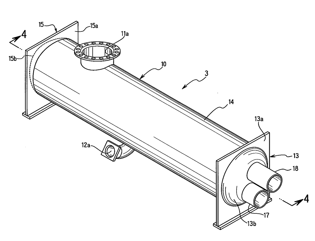
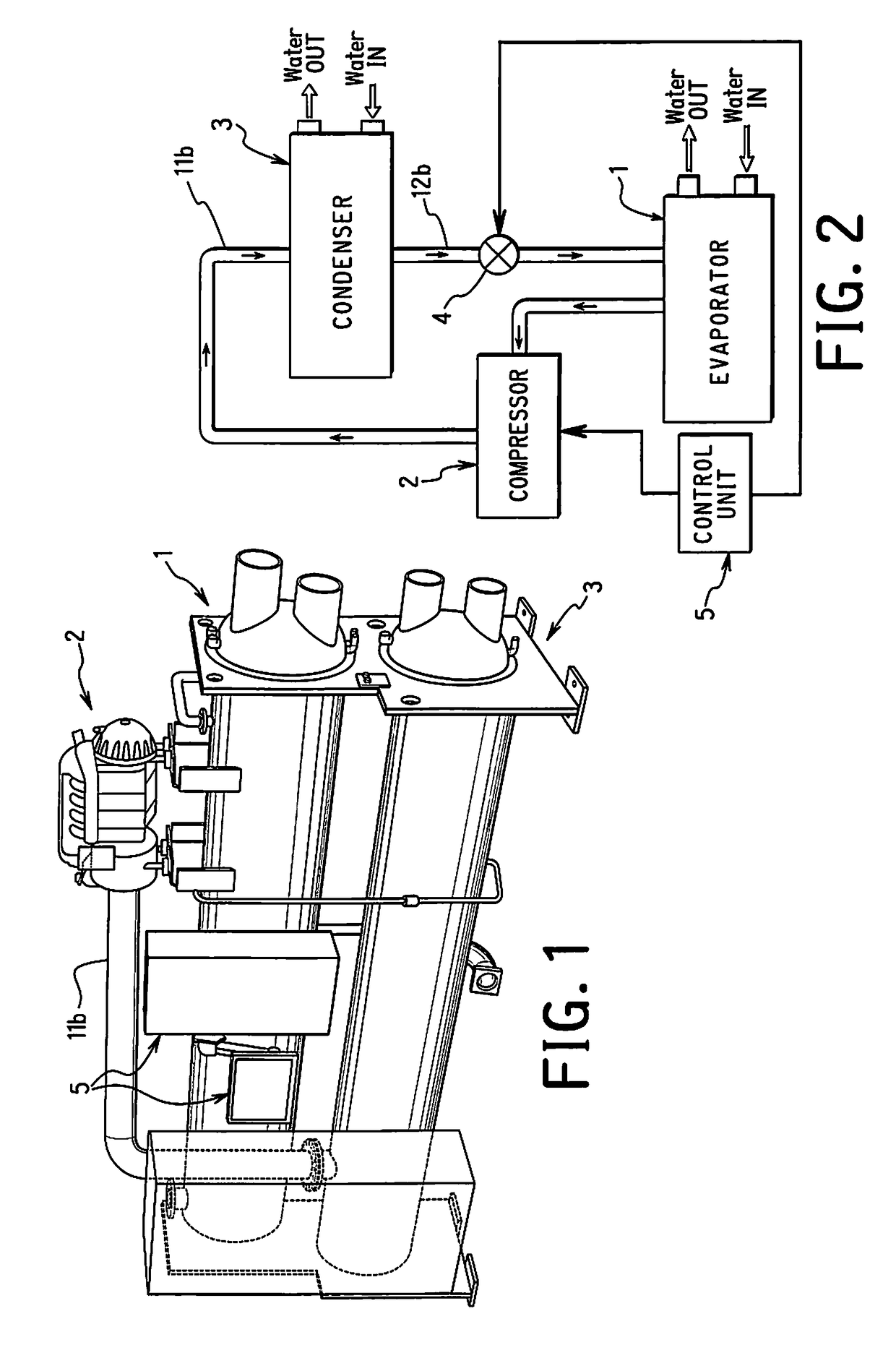
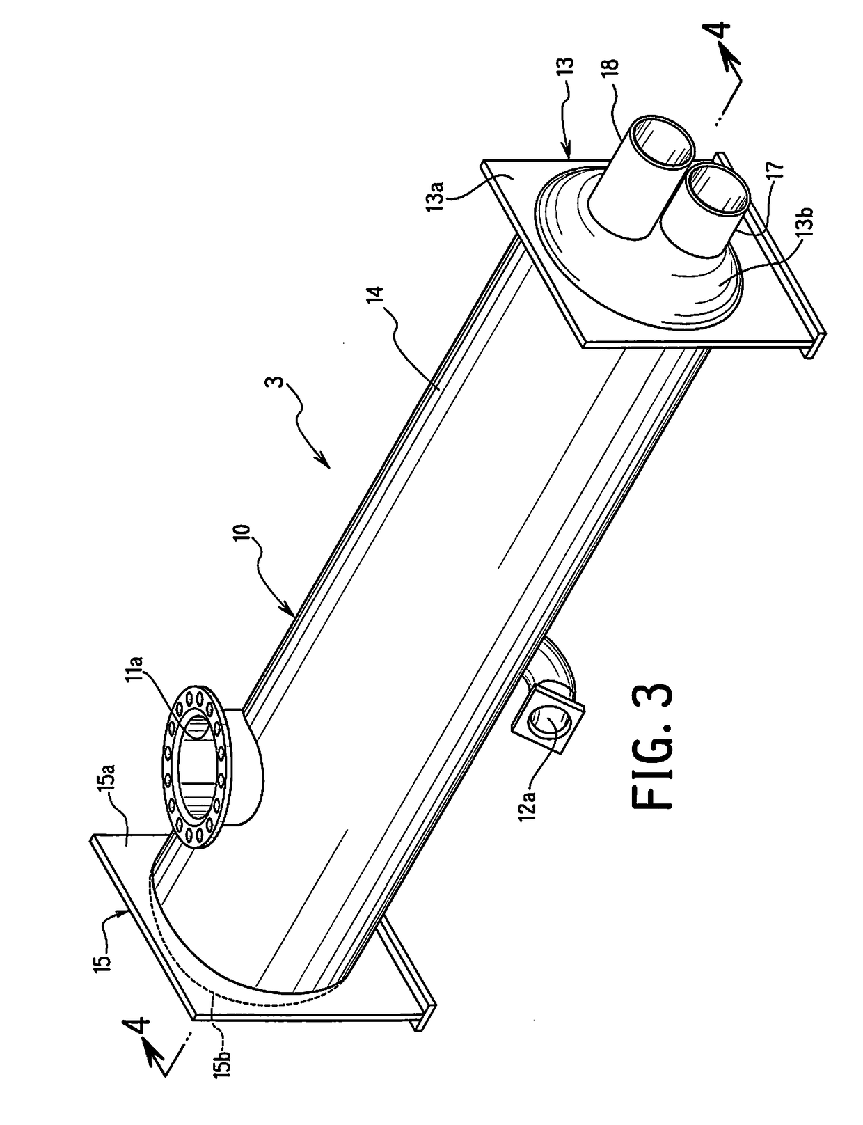
[0025]Referring initially to FIGS. 1 and 2, a vapor compression system including a condenser 3 according to an embodiment will be explained. As seen in FIG. 1, the vapor compression system according to the embodiment is a chiller that may be used in a heating, ventilation and air conditioning (HVAC) system for air-conditioning of large buildings and the like. The vapor compression system of the embodiment is configured and arranged to remove heat from liquid to be cooled (e.g., water, ethylene glycol, brine, etc.) via a vapor-compression refrigeration cycle, and to add heat to liquid to be heated ...


PUM

PropertyMeasurementUnit
angleaaaaaaaaaa
angleaaaaaaaaaa
GWPaaaaaaaaaa

Abstract

A condenser for a vapor compression system includes a shell, a tube bundle, and a tube support structure. The shell has a refrigerant inlet and a refrigerant outlet. The tube bundle includes a plurality of heat transfer tubes disposed inside the shell. Refrigerant discharged from the refrigerant inlet is supplied onto the tube bundle. The heat transfer tubes extend generally parallel to the longitudinal center axis of the shell. The tube support structure is configured and arranged to support the plurality of heat transfer tubes in the tube bundle within the shell. The tube support structure includes at least one tube support plate inclined relative to a vertical direction perpendicular to the longitudinal center axis of the shell.

Description

BACKGROUND OF THE INVENTIONField of the Invention[0001]This invention generally relates to a condenser adapted to be used in a vapor compression system. More specifically, this invention relates to a condenser with a tube support structure.Background Information[0002]Vapor compression refrigeration has been the most commonly used method for air-conditioning of large buildings or the like. Conventional vapor compression refrigeration systems are typically provided with a compressor, a condenser, an expansion valve, and an evaporator. The compressor compresses refrigerant and sends the compressed refrigerant to the condenser. The condenser is a heat exchanger that allows compressed vapor refrigerant to condense into liquid. A heating / cooling medium such as water typically flows through the condenser and absorbs heat from the refrigerant to allow the compressed vapor refrigerant to condense. The liquid refrigerant exiting the condenser flows to the expansion valve. The expansion valve ...

Claims


Application Information

Patent Timeline
Patent Type & Authority Applications(United States)
IPC IPC(8): F25B39/00F28F9/013
CPCF25B39/00F28F9/0131F25B2339/047F25B2339/046F25B39/04F28F2009/228B01D5/0009B01D5/009F28F17/005F28B1/02F28B9/08F28D7/16F28D2021/0063F28D2021/007F28F2009/226B01D1/04B01D1/28F25B25/005F28D7/1676F28D7/1607
Inventor MOREAUX, LOUIS A.
Owner DAIKIN IND LTD
Why Eureka
Try Eureka