

Anti-reflective film and manufacturing method thereof
a technology of anti-reflective film and manufacturing method, which is applied in the direction of instruments, synthetic resin layered products, optical elements, etc., can solve the problems of deteriorating screen sharpness, difficult to increase scratch resistance, and deteriorating scratch resistan
Active Publication Date: 2018-08-16
LG CHEM LTD
View PDF7 Cites 14 Cited by
- Summary
- Abstract
- Description
- Claims
- Application Information
AI Technical Summary
Benefits of technology
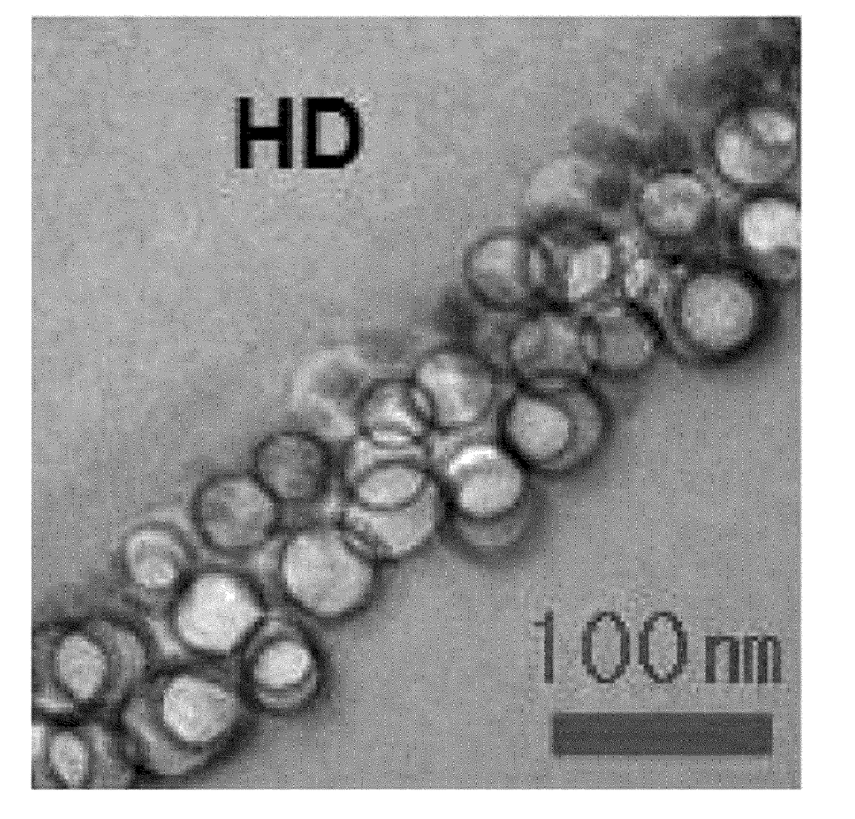
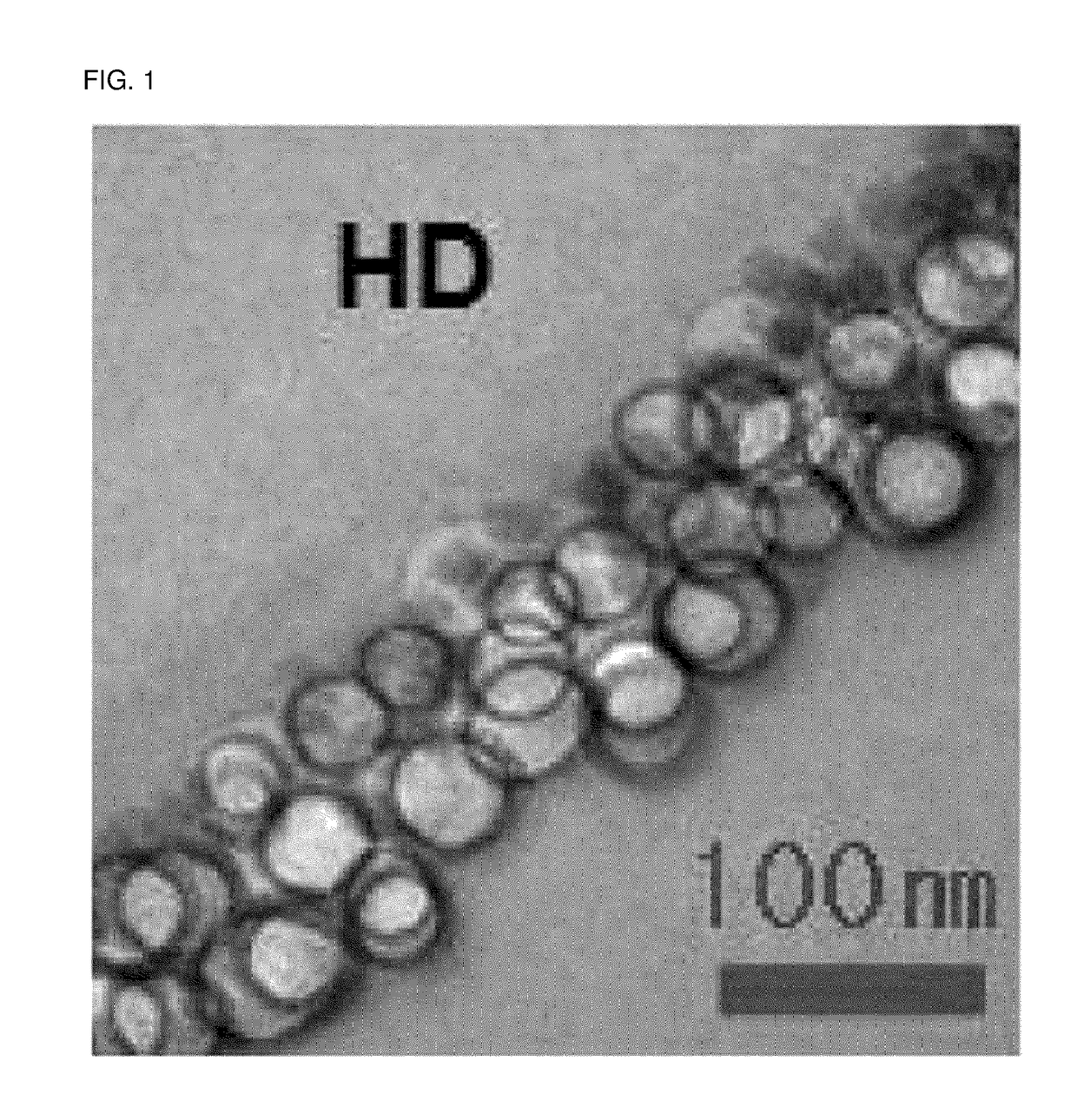
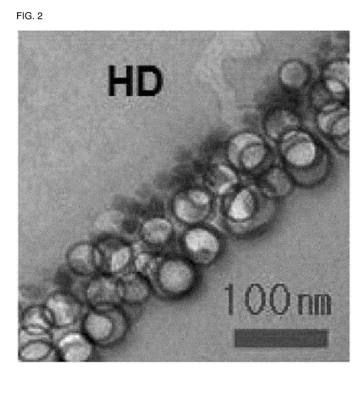
The patent describes an anti-reflective film that has low reflectance, high light transmittance, high scratch-resistance, and anti-fouling properties. It also enhances the sharpness of a screen of a display device. The film has a hard coating layer with a low-refractive layer on its surface. The low-refractive layer contains hollow inorganic nanoparticles and solid inorganic nanoparticles dispersed in a binder resin. The ratio of solid inorganic nanoparticles to hollow inorganic nanoparticles is controlled to achieve the desired properties of the film. The density difference between the two types of nanoparticles is important and affects the film's performance. The patent also provides a manufacturing method for this anti-reflective film.
Problems solved by technology
However, due to the unevenness of the surface, the sharpness of the screen deteriorates.
However, in the method of forming the above-described plurality of layers, the interfacial adhesion between the various layers may be weak, thereby deteriorating the scratch resistance.
However, in such a case, it is difficult to increase scratch resistance while also decreasing the reflectance of the low-refractive layer, thereby significantly reducing the anti-fouling property of a surface of the low-refractive layer.
Method used
View moreImage
Smart ImageViewing Examples

Examples
examples
[0148]The present invention will be described in more detail through the following Examples. However, the following Examples are only to exemplify the present invention, and contents of the present invention are not limited by the following Examples.
preparation example
Preparation Example: Manufacturing of Hard Coating Layer
[0149]A salt-type antistatic hard coating solution (KYOEISHA Chemical Co., Ltd., solid content: 50 wt %, product name: LJD-1000) was coated on a triacetyl cellulose film using a #10 Mayer bar, dried at 90° C. for 1 minute, and irradiated with UV light (150 mJ / cm2), thereby manufacturing a hard coating layer having a thickness of about 5 to 6 μm.
examples 1 to 5
f Anti-Reflective Film
Login to View More PUM
| Property | Measurement | Unit |
|---|---|---|
| density | aaaaa | aaaaa |
| particle diameter | aaaaa | aaaaa |
| temperature | aaaaa | aaaaa |
Abstract
Described herein is an anti-reflective film including: a hard coating layer; and a low-refractive layer containing a binder resin and hollow inorganic nanoparticles and solid inorganic nanoparticles dispersed in the binder resin. The hollow and solid inorganic particles are dispersed in the low-refractive layer such that the amount of the solid inorganic nanoparticles positioned close to an interface between the hard coating layer and the low-refractive layer is larger than that of the hollow inorganic nanoparticles. Also described is a manufacturing method of the anti-reflective film including: applying a resin composition containing a photopolymerizable compound or a (co)polymer thereof, a fluorine-containing compound including a photoreactive functional group, a photoinitiator, hollow inorganic nanoparticles, and solid inorganic nanoparticles on a hard coating layer, and drying the applied resin composition at a temperature of 35° C. to 100° C.; and photocuring the dried resin composition.
Description
CROSS-REFERENCE TO RELATED APPLICATION[0001]This application is a Continuation Bypass of International Application No. PCT / KR2016 / 012591, filed on Nov. 3, 2017, and claims priority to, and the benefit of, Korean Patent Application No. 10-2015-0154591 filed in the Korean Intellectual Property Office on Nov. 4, 2015, and Korean Patent Application No. 10-2016-0142886 filed in the Korean Intellectual Property Office on Oct. 31, 2016, the entire contents of which are incorporated herein by reference.TECHNICAL FIELD[0002]The present invention relates to an anti-reflective film and a manufacturing method thereof. More particularly, the present invention relates to an anti-reflective film capable of having low reflectance and high light transmittance, while simultaneously imparting high scratch-resistance and anti-fouling property, and enhancing the sharpness of a screen of a display device, and a manufacturing method thereof.BACKGROUND OF THE INVENTION[0003]In general, an anti-reflective f...
Claims
Login to View More Application Information
Patent Timeline
 Patent Type & AuthorityApplications(United States)
IPC IPC(8): G02B1/111G02B1/14C08J7/04C09D4/00C08J7/043C08J7/044C08J7/046
CPCG02B1/111G02B1/14C08J7/042C09D4/00C08J2301/02C08J2435/02C08K7/26C08K3/36B32B27/08C08J7/043C08J7/046C08J7/044B32B2307/416B32B2307/418B32B7/023B32B27/20B32B5/145B32B5/16
InventorBYUN, JIN SEOKKIM, HEONKIM, BOO KYUNGJANG, SEOK HOONCHANG, YEONG RAE
OwnerLG CHEM LTD