
Embedded rotary micro pump, its method of integration and motion control

a technology of rotary micro pumps and embedded parts, which is applied in the direction of machines/engines, liquid fuel engines, and positive displacement liquid engines, etc., can solve the problems of reducing the efficiency of devices, changing the surface tension properties, and most conventional pumping methods based on periodic movements of mechanical actuators, so as to achieve smooth control of flow rate and pump coolant fluids. continuous and efficient

Active Publication Date: 2018-08-23
CITROGENE INC
View PDF2 Cites 5 Cited by
  • Summary
  • Abstract
  • Description
  • Claims
  • Application Information

AI Technical Summary

Benefits of technology

The patent text describes a new invention that uses circular disks to pump fluids in small channels. The disks spin about their axis and create a boundary shear stress, which causes a velocity gradient and fluid flow. The flow is steady and continuous, without any pulses. The pumping mechanism works regardless of the properties of the fluid, and can be controlled by external fields. The disks can be rotated at different speeds, and the flow rate can be adjusted by changing the speed. This invention can be used to cool microprocessors, and can pump coolant fluids smoothly and efficiently.

Problems solved by technology

Fluid pumping in micro channels is a technological challenge because in sub-millimeter scales viscous forces dominate inertial ones and most conventional pumping methods based on periodic movements of mechanical actuators fail.
For example, the addition of proteins and other biological material to samples can significantly change the surface tension properties and reduce the efficiency of the device.
Moreover, the application of electroosmotic pumps is limited to conducting liquids and these pumps suffer from permittivity, zeta, and bubble formation problems.
In digital PCR (Polymerase Chain Reaction) applications where droplets of water-based samples are carried by non-conducting and non-polar oil and various surfactants are present in the mixture, electroosmotic and electrowetting techniques would fail.

Method used


Image

  • Embedded rotary micro pump, its method of integration and motion control
  • Embedded rotary micro pump, its method of integration and motion control
  • Embedded rotary micro pump, its method of integration and motion control

Examples


Embodiment Construction

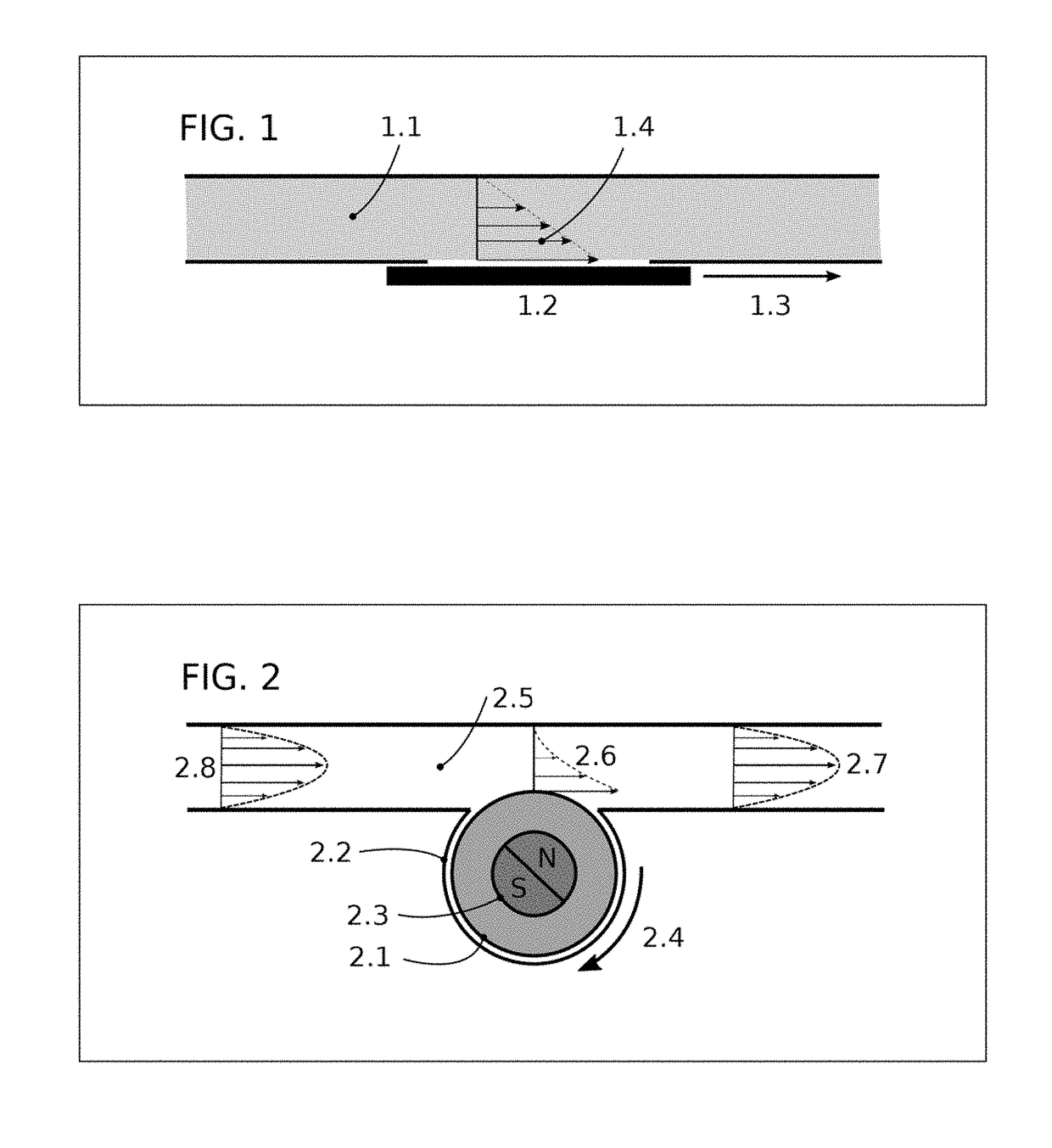
[0023]The present invention provides a method and an apparatus to generate fluid flow in micro channels. Pressure-driven fluid flow in straight micro channels is laminar where fluid elements move along straight lines. Across the channel cross section, however, the streaming velocity varies due to shear stresses between fluid layers. Fluid elements near channel walls have smaller speeds than those moving at or near the channel centerline. In the idealistic case of no-slip boundary conditions (zero velocity at the walls) and in a channel of circular cross section, the flow profile is parabolic. In such conditions, fluid elements at the channel centerline have the maximum speed.

[0024]FIG. 1 illustrates a micro channel filled the fluid 1.1. In the absence of any pressure gradient along the channel, if one of the walls (e.g., wall 1.2) moves parallel to the channel centerline in the direction 1.3, a shearing layer will be created at the channel's boundary generating velocity profile 1.4....


PUM


Abstract

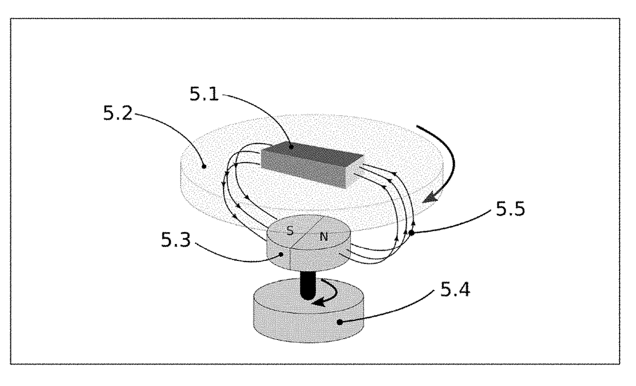
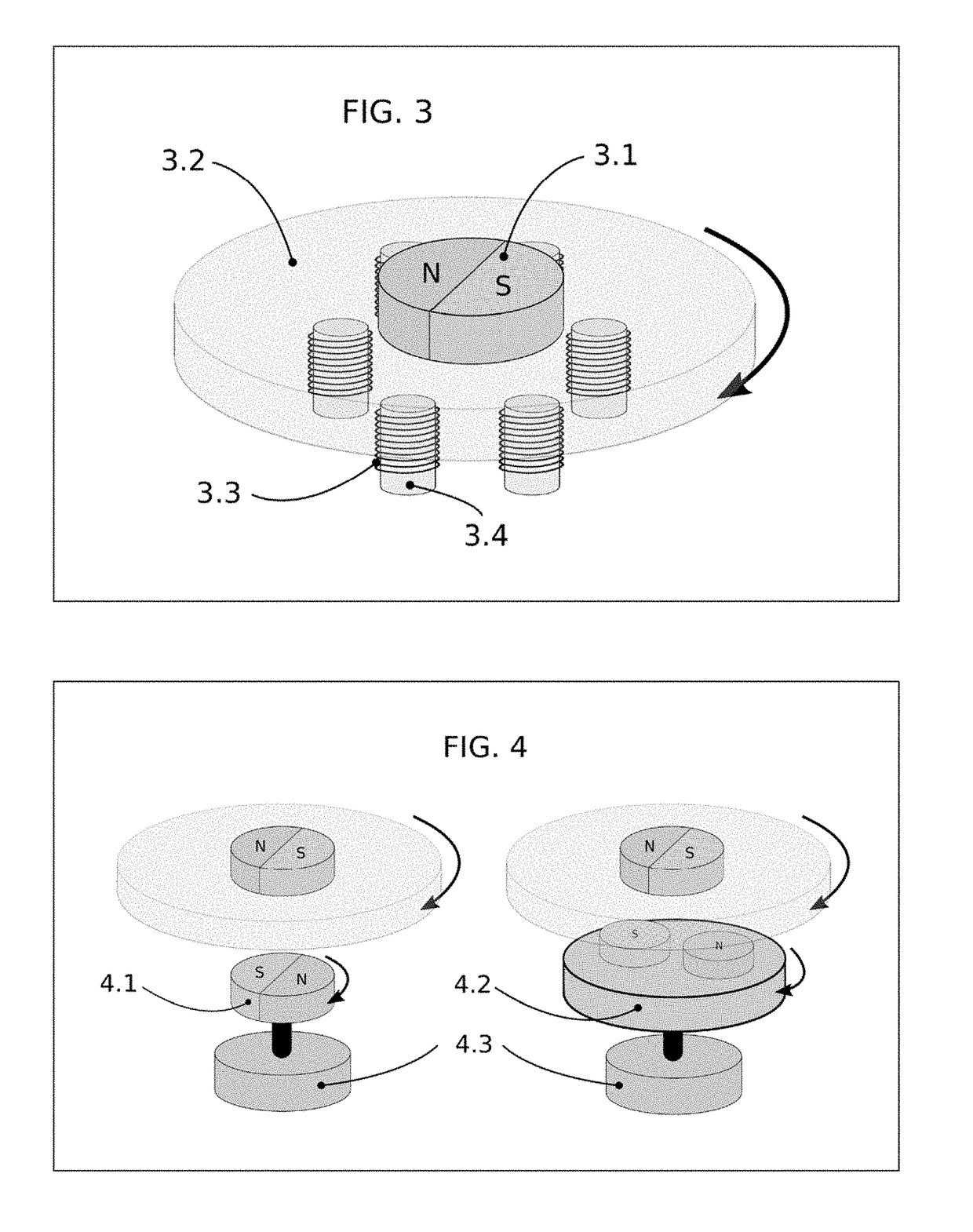
A micro pumping mechanism is proposed to generate flow in micro channels of micro fluidic devices and three dimensional microprocessors cooled by the flow of coolant fluids. The proposed micro pump comprises a rotating disk inside a chamber, which overlaps with the fluidic micro channel. The rotating disk induces a shear flow across the micro channel, transporting fluid elements in the direction of the rotation of the disk. The disk can be rotated by external magnetic or electric fields as in direct drive, induction, or electrostatic motors.

Description

CROSS-REFERENCE TO RELATED APPLICATIONS[0001]This application claims benefit of U.S. Patent Provisional application No. 62 / 461,982 filed 22 Feb. 2017. All subject matter set forth in provisional application No. 62 / 461,982 filed 22 Feb. 2017 is hereby incorporated by reference into the present application as if fully set forth herein.BACKGROUND OF THE INVENTIONField of the Invention[0002]This invention relates to rotary pumps and more particularly to an embedded rotary micro pump.Description of the Related Art[0003]Fluid pumping in micro channels is a technological challenge because in sub-millimeter scales viscous forces dominate inertial ones and most conventional pumping methods based on periodic movements of mechanical actuators fail. Flow generation in micro channels is achieved by two general classes of pumps: (i) external pumps and (ii) integrated pumps. Widely-used external pumps are pressure, vacuum, and syringe pumps, which can induce continuous and steady flow rates. Most ...

Claims


Application Information

Patent Timeline
IPC IPC(8): F04D5/00F04D13/06A61M60/237A61M60/419A61M60/827
CPCF04D5/001F04D13/06F04D13/024F04D13/0666F04D29/048F04D29/047F05D2250/82A61M60/205A61M60/419F04B19/006A61M60/237A61M60/827
Inventor JALALI, MIR ABBASHOSSEINI, S. ABBASTORK, AMIR
Owner CITROGENE INC
Learn More