
System, apparatus and method for efficient use of solar photovoltaic energy

a photovoltaic energy and solar energy technology, applied in the direction of thermal-pv hybrid energy generation, instruments, heating types, etc., can solve the problems of water heating, water heating consumes about a quarter of a typical household's electricity usage, and water heating also makes up a significant portion of the electricity consumption

Active Publication Date: 2018-08-23
RHEEM AUSTRALIA PTY LIMITED
View PDF20 Cites 16 Cited by
  • Summary
  • Abstract
  • Description
  • Claims
  • Application Information

AI Technical Summary

Benefits of technology

This patent is for a system that controls the energy usage of a water heater. It includes a controller, a modulator, and a heating unit with multiple heating elements. The controller monitors the direction of electric current flow and controls the modulator to deliver power to the first heating element. The system also has an attachment flange that is sealed to a water heater tank. The technical effect is a system that minimizes or eliminates current flow to the utility grid and optimizes energy usage for a water heater.

Problems solved by technology

Similarly, wind generators are subject to wind fluctuations.
Water heating consumes about a quarter of a typical household's electricity usage for households equipped with electric water heaters.
Water heating also makes up a significant portion of gas consumption for households with gas water heating.
Solar thermal water heaters have a disadvantage in relation to solar electric water heaters in that, at low levels of insolation, if there is insufficient solar input to heat the heat transfer fluid above the temperature of the water in the tank, no useful energy can be collected.
A disadvantage of DC is that it is difficult to interrupt a DC current, and connector contacts can be eroded by sparks on switching the current off.
However, it has the problem that modulation systems may generate unacceptable amounts of electromagnetic interference or cause fluctuations in the power system.

Method used


Image

  • System, apparatus and method for efficient use of solar photovoltaic energy
  • System, apparatus and method for efficient use of solar photovoltaic energy
  • System, apparatus and method for efficient use of solar photovoltaic energy

Examples


Embodiment Construction

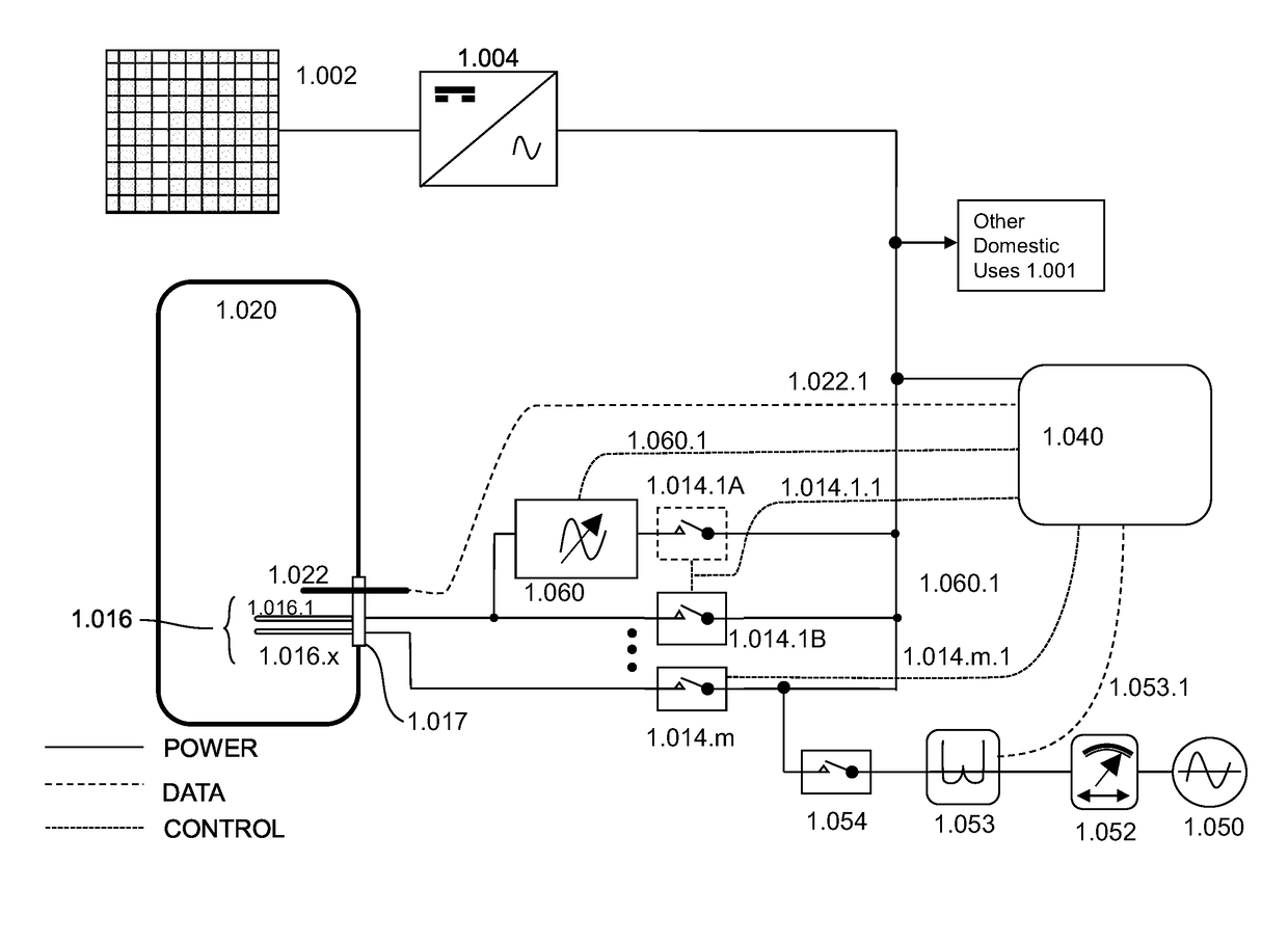
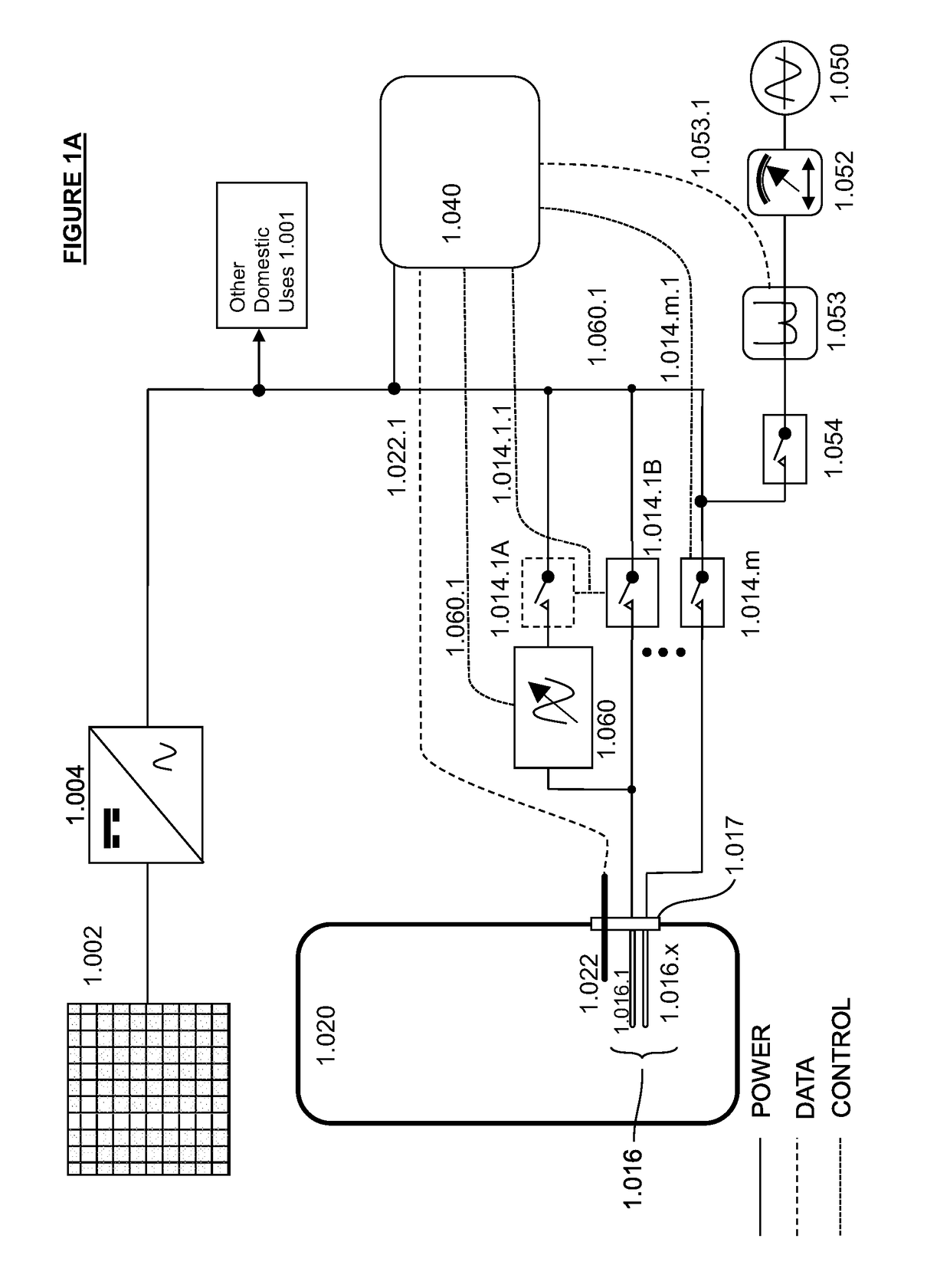
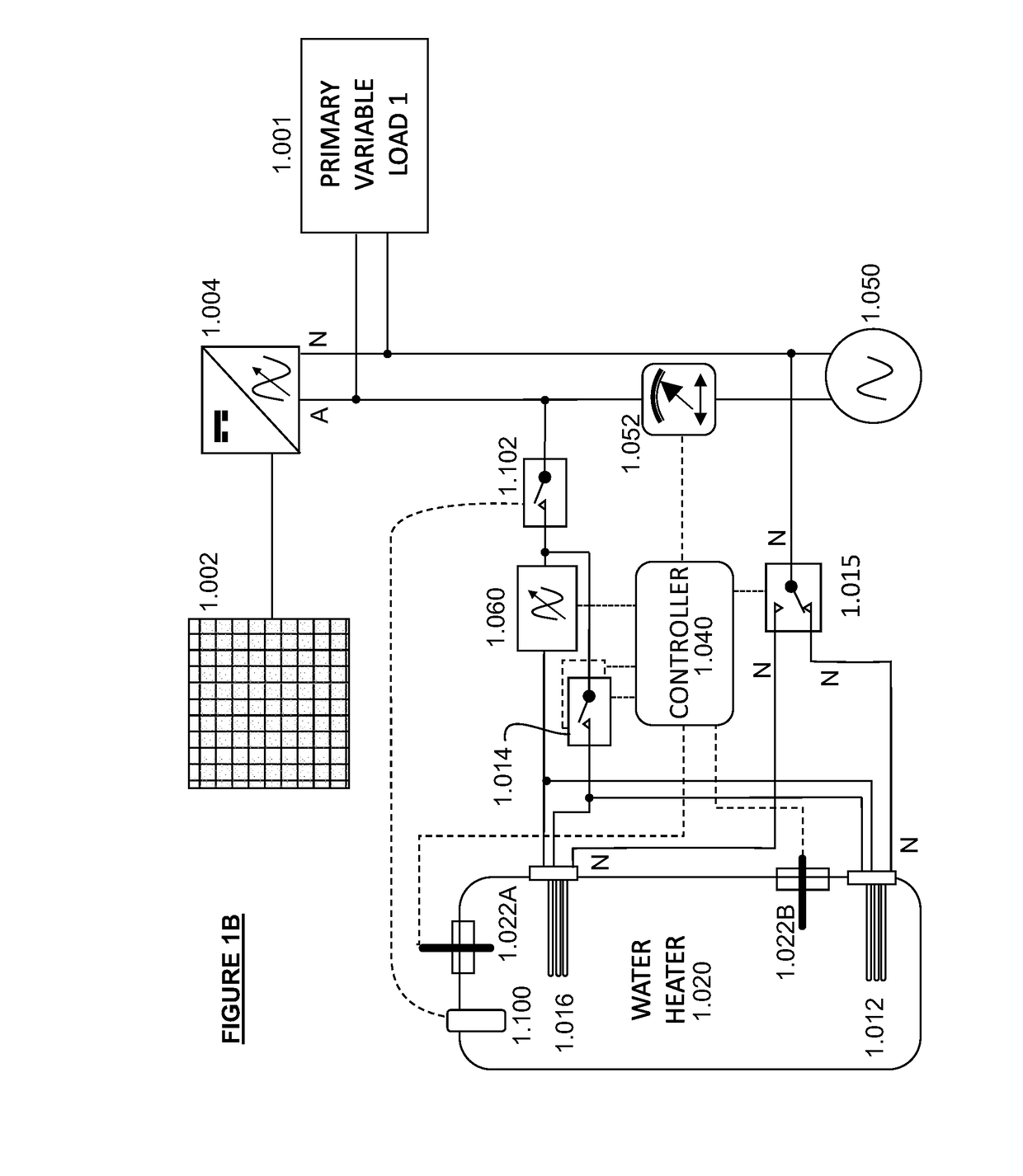
[0069]The PV water heating system illustrated in FIG. 1 includes a PV collector (1.002), an inverter (1.004), a water tank (1.020), a heating unit (1.016) having two or more elements (1.016.1 . . . 1.016.x), a temperature sensor (1.022), a number of switches, (1.014.1 to 1.014.m), each associated with a heating element, an AC modulator (1.060), utility grid supply (1.050, bidirectional utility grid meter (1.052), utility grid switch 1.054), and controller (1.040). Because heating element 1.016.1 is powered via the modulator, the switch (1.014.1A) is optional, as the modulator output can be reduced to zero.

[0070]The PV collector (1.002) is connected to inverter (1.004) which converts the DC voltage output from the PV collector to an alternating voltage supply suitable for delivery to the utility grid. A water storage tank (1.020) has a first multi-element heating unit which is inserted in the lower portion of the tank via a sealed flange (1.017). While temperature sensor (1.022) is s...


PUM


Abstract

A solar photovoltaic (PV) water heating system includes a tank (1.020) including at least a first heating unit (1.016) having at least first and second heating elements (1.016.1 . . . 1.016.x), at least one of which is switchable (1.014.1A . . . 1.014.1m); a PV solar collector (1.002); an inverter (1.004) adapted to convert the output from the PV collector to an alternating power supply; a modulator (1.060) to modulate the alternating power supply from the inverter; a controller (1.040) adapted to control the modulator and the switching of the or each switchable heating element; wherein the controller is adapted to control the modulator and the switchable heating elements to maximize the energy drawn from the PC collector.

Description

CLAIM OF PRIORITY[0001]This application claims priority to Australian Patent Application No. 2016250449, filed Oct. 28, 2016, the entire disclosure of which is incorporated by reference herein.BACKGROUND OF THE INVENTION[0002]This invention relates to the utilization of renewable energy. The sources of some forms of renewable energy, such as solar and wind, have a highly variable output. For example, solar collector output varies with the amount of insolation impinging on the collector, and this varies gradually with the position of the sun and rapidly with the passing of clouds. Similarly, wind generators are subject to wind fluctuations. While the invention is applicable to the different forms of renewable energy, the invention will be described primarily in the context of a solar photovoltaic energy system.[0003]With the adoption of smart electricity meters, power companies can charge different tariffs during periods of the day according to the load on the power generator equipme...

Claims


Application Information

Patent Timeline
IPC IPC(8): F24D19/10F24H1/18F24D17/00G05F1/67
CPCF24D19/1057F24H1/185F24D17/0068G05F1/67F24D2200/02F24D2200/14F24D2200/32F24D2200/08H02S50/00H02S10/20H02J7/35H02J2300/22H02J2310/12H02J2310/14H02J2300/24H02J3/381H02J3/14Y02E10/60Y02B30/70Y02E10/56Y04S20/242Y04S20/244Y02B70/30Y02E70/30F24H15/407F24H15/164F24H15/296F24H15/225F24H15/37F24H15/292H02S40/32H02S40/38H02S40/44H02J3/38
Inventor STEPA, GRANT ANDREWKERR, PETER ROBERT
Owner RHEEM AUSTRALIA PTY LIMITED
Learn More