
Microelectromechanical scalable bulk-type piezoresistive force/pressure sensor

a piezoresistive force and microelectromechanical technology, applied in the field of microelectromechanical scalable bulk-type piezoresistive force/pressure sensor, can solve the problems of low sensitivity, limited miniaturization possibility, and complex package structure requirements

Active Publication Date: 2018-08-23
STMICROELECTRONICS SRL
View PDF0 Cites 9 Cited by
  • Summary
  • Abstract
  • Description
  • Claims
  • Application Information

AI Technical Summary

Benefits of technology

This invention is a microelectromechanical sensor that is easy to make, can be customized easily, is very sensitive, and has a high detection ability. This patent also describes a method for making this sensor.

Problems solved by technology

Although commonly used, the drawbacks of these sensors are a low sensitivity and a limited possibility of miniaturization.
A drawback of these sensors is the requirement of complex package structures, in order to convert an applied load to a stress acting on the silicon die and the integrated piezoresistor.
These sensors are therefore expensive and generally do not allow easy customization, in particular with respect to the range of applied load.
Although having a good sensitivity and allowing miniaturization, also this sensor suffers from the above discussed drawback of having an expensive and complex manufacturing process and package design to convert an externally applied pressure to a force concentrated on the silicon die.

Method used


Image

  • Microelectromechanical scalable bulk-type piezoresistive force/pressure sensor
  • Microelectromechanical scalable bulk-type piezoresistive force/pressure sensor
  • Microelectromechanical scalable bulk-type piezoresistive force/pressure sensor

Examples


Embodiment Construction

[0030]One or more embodiments are directed to exploiting the piezoresistivity effect of bulk silicon to design a new MEMS (Micro-Electro-Mechanical System) integrated force / pressure sensor, to sense from few N / bar up to several kN / kbar of external forces / pressures (by scaling up, or down, the corresponding size, and due to the high strength of silicon material).

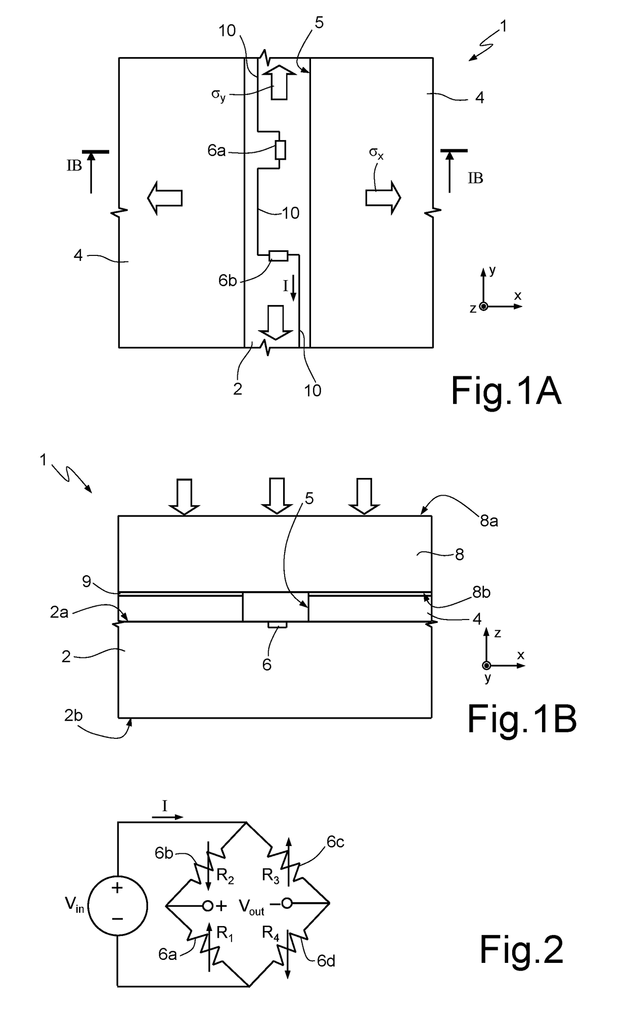
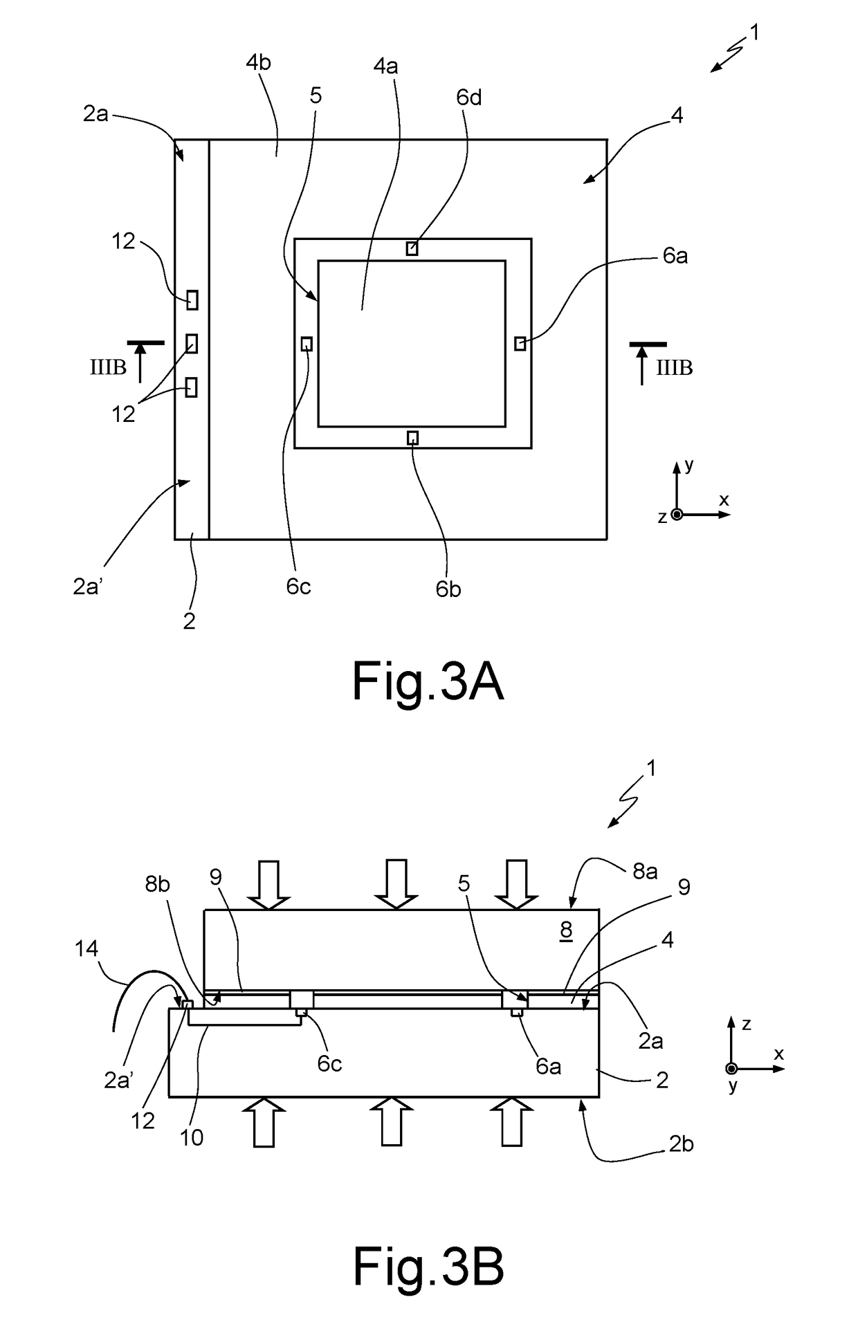
[0031]As will be discussed in detail in the following, the sensor comprises two bodies (dies) of semiconductor material, in particular silicon, which are bonded together, with sensing elements, in particular piezoresistor elements, being formed at a top surface of a bottom die (sensor die).

[0032]A conversion layer, of a suitable material as described below, is placed on the sensor die, with a special pattern in order to convert applied vertical force / pressure into a desired planar stress, which is sensed by the piezoresistor elements.

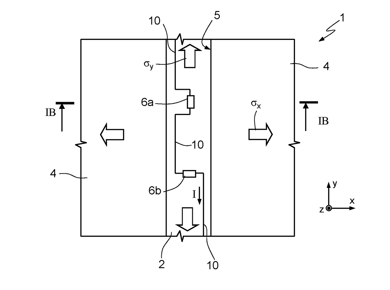
[0033]Referring first to FIGS. 1A and 1B, the structure and operating principle of a force / pr...


PUM


Abstract

A microelectromechanical force / pressure sensor has: a sensor die, of semiconductor material, having a front surface and a bottom surface, extending in a horizontal plane, and made of a compact bulk region having a thickness along a vertical direction, transverse to the horizontal plane; piezoresistive elements, integrated in the bulk region of the sensor die, at the front surface thereof; and a cap die, coupled above the sensor die, covering the piezoresistive elements, having a respective front surface and bottom surface, opposite to each other along the vertical direction, the bottom surface facing the front surface of the sensor die. A conversion layer is arranged between the front surface of the sensor die and the bottom surface of the cap die, patterned to define a groove traversing its entire thickness along the vertical direction; the piezoresistive elements are arranged vertically in correspondence to the groove and the conversion layer is designed to convert a load applied to the front surface of the cap die and / or bottom surface of the sensor die along the vertical direction into a planar stress distribution at the groove, acting in the horizontal plane.

Description

BACKGROUNDTechnical Field[0001]The present disclosure relates to a microelectromechanical scalable bulk-type piezoresistive force / pressure sensor.Description of the Related Art[0002]There are several applications, e.g., in the industrial or automotive fields, requiring use of force / pressure sensors with a high full-scale value, for measuring high-range load (force or pressure) values, e.g., up to 10 kN or higher.[0003]Known sensor solutions for sensing high-range loads generally envisage use of high strength metallic load cells, including different kinds of strain gauges as sensing elements. The strain gauge sensing elements detect the geometric deformation of the core to which they are coupled via changes in electrical resistance.[0004]Although commonly used, the drawbacks of these sensors are a low sensitivity and a limited possibility of miniaturization.[0005]Integrated pressure sensors, made using semiconductor technology, are also known, using piezoresistive elements integrated...

Claims


Application Information

Patent Timeline
IPC IPC(8): G01L1/18H01C10/10H01C17/00G01L9/06
CPCG01L1/18H01C10/10H01C17/00G01L9/06B81B1/00B81B7/02B81C1/00015B81B2201/02G01L9/0002G01L19/146G01L1/26
Inventor ABBASI GAVARTI, MOHAMMADCALTABIANO, DANIELEPICCO, ANDREAPOMARICO, ANNA ANGELAROSELLI, GIUDITTABRAGHIN, FRANCESCO
Owner STMICROELECTRONICS SRL
Learn More