Capacitive pressure sensor

Active Publication Date: 2018-08-23
YAMATAKE HONEYWELL CO LTD
View PDF12 Cites 4 Cited by
  • Summary
  • Abstract
  • Description
  • Claims
  • Application Information

AI Technical Summary

Benefits of technology

[0017]As described above, in the present disclosure, the distance between the pressure receiving surface of the diaphragm and the surface facing the pressure receiving surface is smaller than the mean free path of the measured medium in substantially the entire region of the pressure receiving surface. Therefore, in substantially the entire region of the

Problems solved by technology

In the film deposition or etching process, deposited films or byproducts produced during the process (hereinafter, these substances are referred to as “contaminants”) accumulate more or less inside the chambers, pipes, and pumps and cause various problems.
Accumulation of contaminants inside the diaphragm gauge that measures and controls gas pressure in the process is known to cause a shift in zero point, chang

Method used


Image

  • Capacitive pressure sensor
  • Capacitive pressure sensor
  • Capacitive pressure sensor

Examples


first embodiment

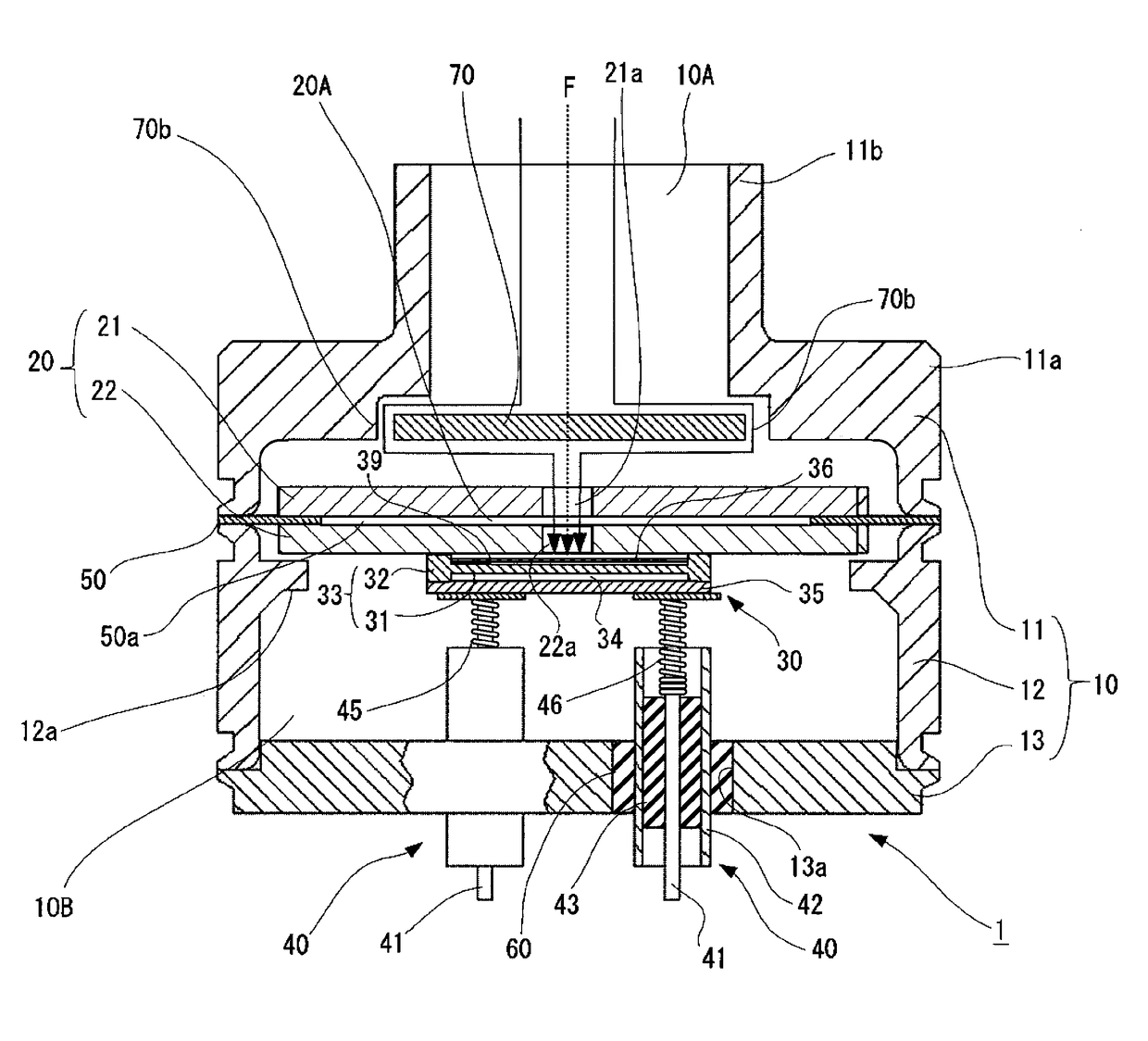
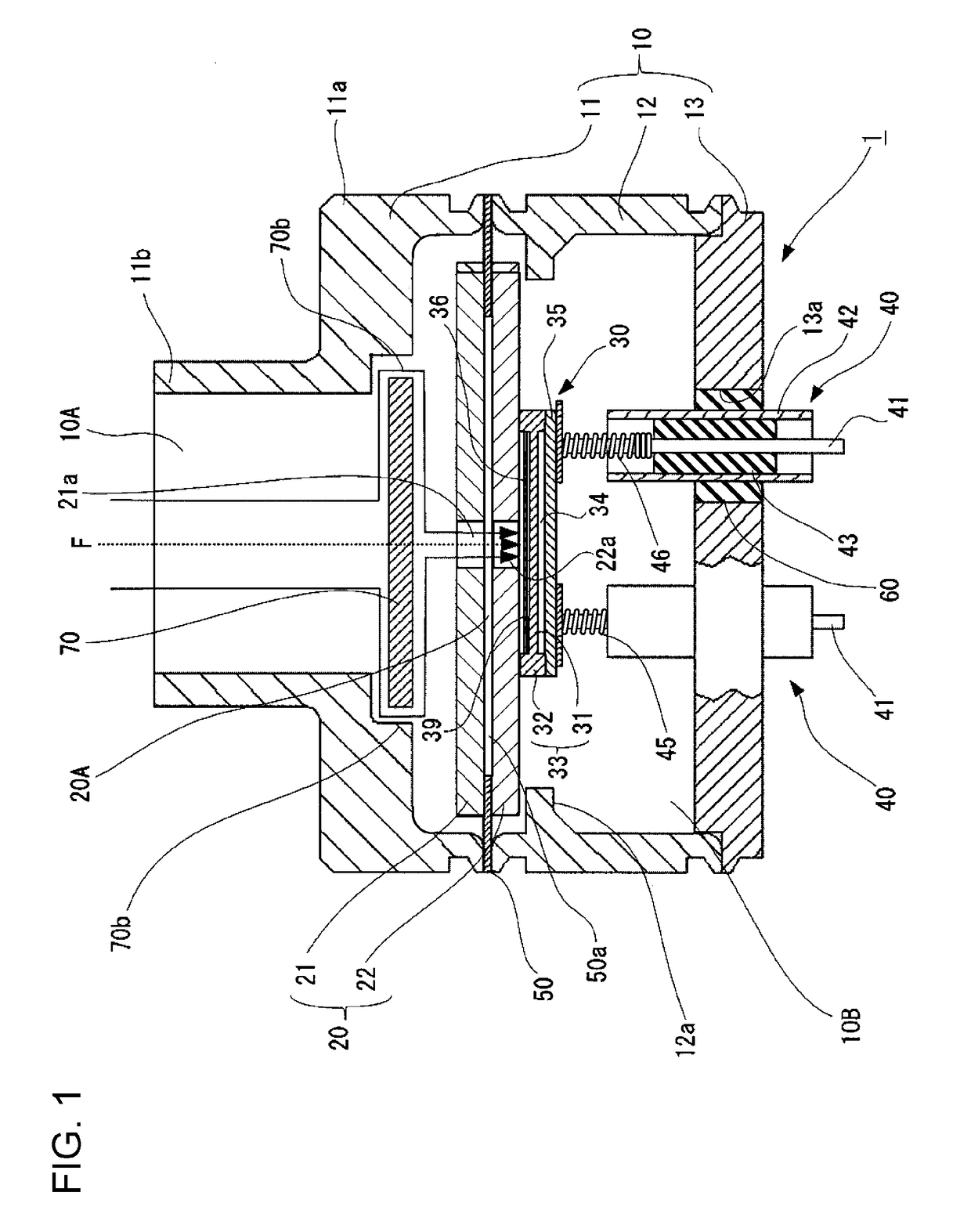
[0044]FIG. 1 is a vertical cross-sectional view of a main part of a diaphragm gauge which is an embodiment of a capacitive pressure sensor according to the present disclosure.

[0045]A diaphragm gauge 1 includes a package 10, a base plate assembly 20 contained in the package 10, a sensor chip 30 also contained in the package 10 and joined to the base plate assembly 20, and electrode lead portions 40 directly attached to the package 10 and configured to electrically connect the interior and exterior of the package 10. The base plate assembly 20 is composed of a first base plate 21 and a second base plate 22, spaced from the package 10, and supported by the package 10 with only a supporting diaphragm 50 therebetween.

[0046]The package 10 includes an upper housing 11, a lower housing 12, and a cover 13. The upper housing 11, the lower housing 12, and the cover 13 are made of metal resistant to corrosion and are joined to one another by welding.

[0047]The upper housing 11 is formed by conne...

second embodiment

[0073]Although the pressure introducing chamber 36 is provided with the baffle plate 39 in the first embodiment, the second embodiment does not include the baffle plate 39. FIG. 4 is a vertical cross-sectional view of a main part of the diaphragm gauge 1 corresponding to FIG. 2. Note that the first base plate 21 is additionally shown in FIG. 4.

[0074]In the second embodiment, the second base plate 22 has a plurality of (four, in this example) discharging holes 22a for discharging the measured medium. The discharging holes 22a communicate with the slit-like space (cavity) 20A and the pressure introducing chamber 36 in the sensor chip 30. FIG. 5 illustrates a positional relationship between the introducing hole 21a formed in the first base plate 21 and the discharging holes 22a formed in the second base plate 22FIG. 5 is a plan view as viewed in the direction of arrow V in FIG. 4.

[0075]As illustrated in FIGS. 4 and 5, the introducing hole 21a in the first base plate 21 and the discharg...

third embodiment

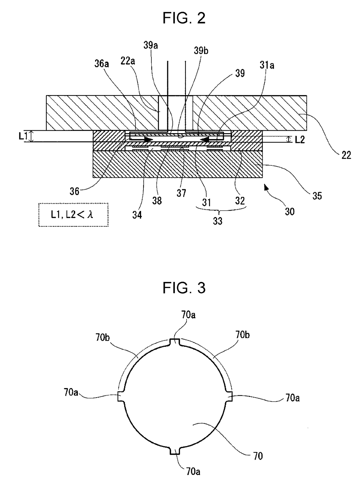
[0079]In the second embodiment (i.e., structure illustrated in FIG. 4), there may be cases where, due to constraints in processing the sensor chip 30, the distance L between the pressure receiving surface 31a of the sensor diaphragm 31 and the inner surface 36a of the pressure introducing chamber 36 cannot be made smaller than the mean free path λ of the measured medium.

[0080]In such a case, as illustrated in FIG. 7, the second base plate 22 may be processed in such a manner that substantially the entire surface thereof facing the pressure receiving surface 31a of the sensor diaphragm 31 becomes a raised surface 22b, so that the distance L between the pressure receiving surface 31a of the sensor diaphragm 31 and the raised surface 22b in the pressure introducing chamber 36 is smaller than the mean free path λ of the measured medium.

[0081]In this case, the distance between the inner surface 36a of the pressure introducing chamber 36 outside the raised surface 22b and the pressure rec...


PUM


Abstract

A pressure introducing chamber is provided with a baffle plate which is positioned with one surface thereof facing in a direction orthogonal to a direction of travel of a measured medium introduced through a pressure introducing hole into the pressure introducing chamber. A first distance between a pressure receiving surface of a sensor diaphragm and an inner surface of the pressure introducing chamber facing the pressure receiving surface and a second distance between the pressure receiving surface of the sensor diaphragm and the other surface of the baffle plate facing the pressure receiving surface are both smaller than a mean free path of the measured medium in the entire region of the pressure receiving surface of the sensor diaphragm.

Description

CROSS-REFERENCE TO RELATED APPLICATIONS[0001]The present application is based on and claims priority to Japanese Application No. 2017-027959, filed Feb. 17, 2017, the entire contents of which are incorporated therein by reference.BACKGROUND1. Field[0002]The present disclosure relates to a capacitive pressure sensor including a sensor chip having a diaphragm structure that detects a capacitance corresponding to pressure of a medium to be measured2. Description of the Related Art[0003]In pressure sensors, including vacuum gauges which are used for example in semiconductor manufacturing facilities, a sensor element including a small diaphragm has been often adopted using a so-called micro-electromechanical systems (MEMS) technique. A main detection principle of this sensor element is that the pre sure of a pressure medium is received by the diaphragm and the resulting displacement of the diaphragm is converted into some type of signal.[0004]For example, as a pressure sensor that uses a...

Claims


Application Information

Patent Timeline
IPC IPC(8): G01L9/00G01L19/06G01M3/16G01L13/02
CPCG01L9/0072G01L19/0636G01M3/16G01L9/0042G01L13/025G01L9/0073G01L9/12G01L19/04G01L7/082G01L9/0005
Inventor ISHIHARA, TAKUYASOEDA, MASARUSEKINE, MASASHI
Owner YAMATAKE HONEYWELL CO LTD
Why Eureka
Try Eureka