Diagnosis device, energy storage apparatus, and diagnosis method

a technology of diagnostic device and energy storage device, which is applied in the direction of engine starters, safety/protection circuits, instruments, etc., can solve the problems of electrical power supply being cut off, method that requires temporary cutoff cannot be performed under use, and overcharge and overdischarge of batteries cannot be prevented, so as to avoid the cutoff of electrical power supply

Active Publication Date: 2018-08-23
GS YUASA INT LTD
View PDF0 Cites 10 Cited by
  • Summary
  • Abstract
  • Description
  • Claims
  • Application Information

AI Technical Summary

Benefits of technology

[0008]The present invention is intended to solve the above-described problem and diagnose current cutoff devices while avoiding cutoff of electrical power supply when a vehicle is traveling.

Problems solved by technology

When such a current cutoff device is in failure, overcharge and overdischarge of the battery cannot be prevented.
However, any method that requires temporary cutoff of electrical power supply cannot be performed under usage in which electrical power needs to be continuously supplied to a system in, for example, an automobile.
Thus, when one of the current cutoff devices is opened for diagnosis while the other is in open failure due to, for example, vibration during traveling, electrical power supply is cut off while the vehicle is traveling since the two current cutoff devices are both opened.
The same problem occurs to the method disclosed in Japanese Patent Laid-open No. 2014-36556.

Method used


Image

  • Diagnosis device, energy storage apparatus, and diagnosis method
  • Diagnosis device, energy storage apparatus, and diagnosis method
  • Diagnosis device, energy storage apparatus, and diagnosis method

Examples


embodiment 1

1. Description of battery

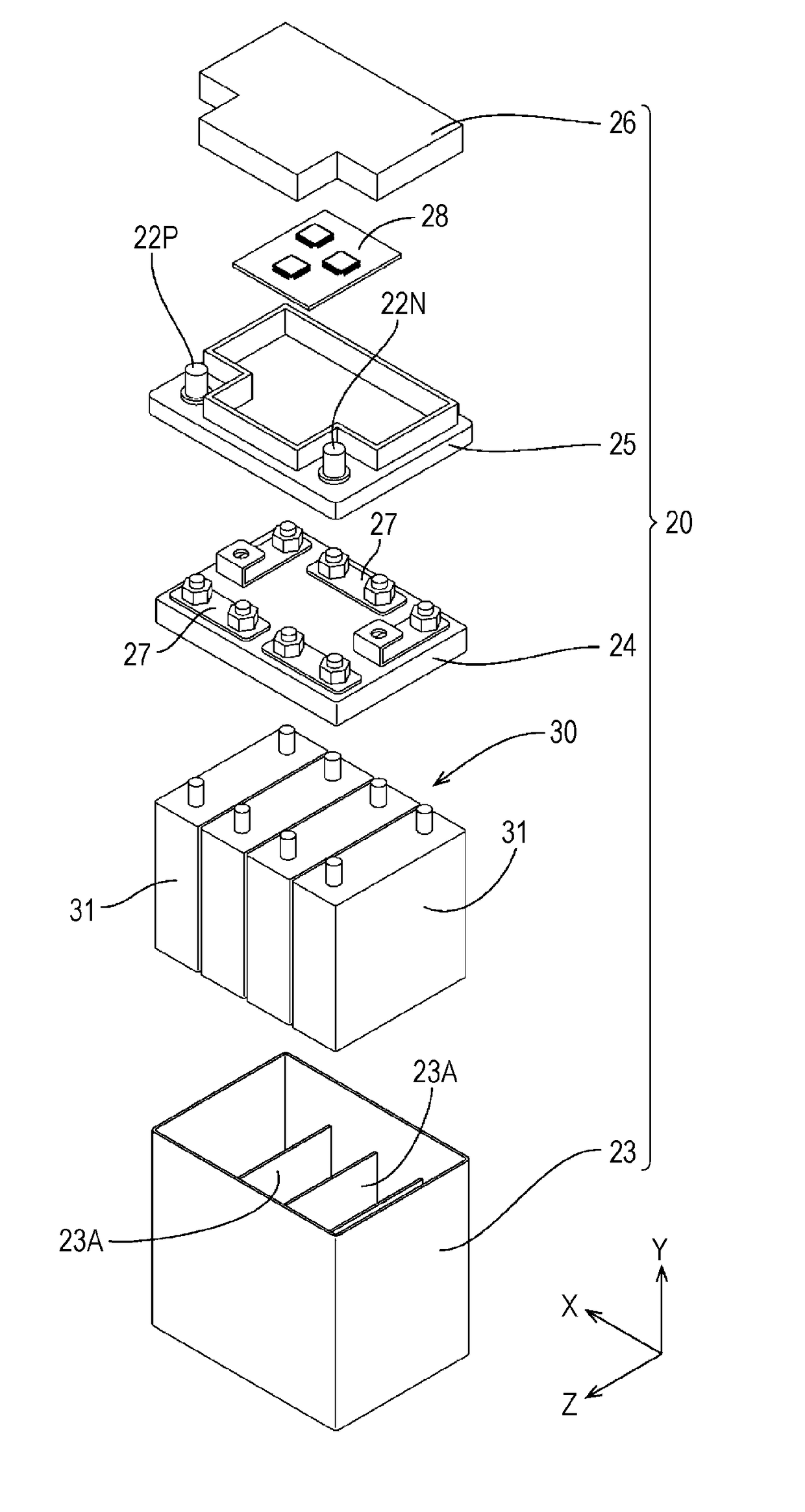
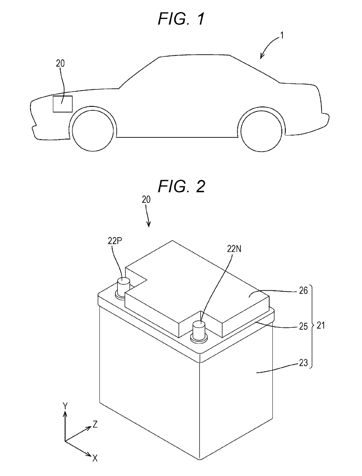
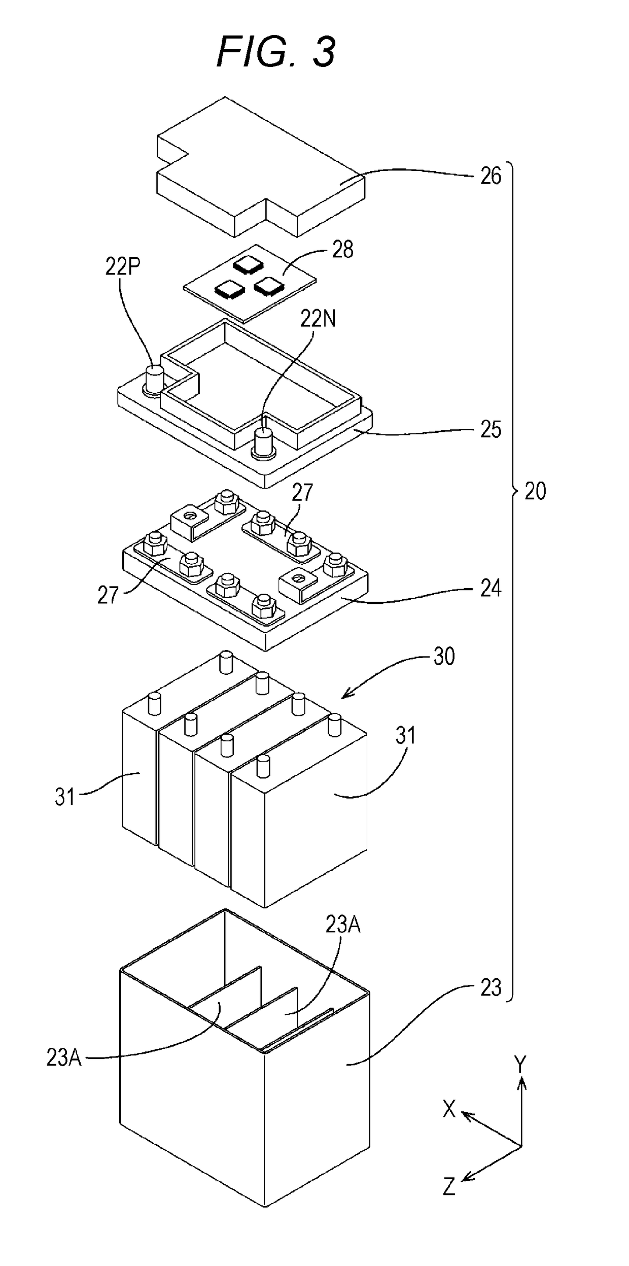
[0035]FIG. 1 is a side view of a vehicle, FIG. 2 is a perspective view of a battery, FIG. 3 is an exploded perspective view of the battery, and FIG. 4 is a block diagram illustrating an electric configuration of the battery.

[0036]As illustrated in FIG. 1, an automobile (hereinafter, an exemplary vehicle) 1 includes a battery (energy storage apparatus) 20. As illustrated in FIG. 2, the battery 20 includes a block-shaped battery case 21 that houses an assembled battery 30 including a plurality of secondary batteries 31 and a control board 28. When FIGS. 2 and 3 are referred to in the following description, a Y direction, an X direction, and a Z direction are taken to be along the vertical direction of the battery case 21, the longitudinal direction of the battery case 21, and the depth direction of the battery case 21, respectively, when the battery case 21 is horizontally placed on an installation surface without tilt.

[0037]As illustrated in FIG. 3, the batte...

embodiment 2

[0098]In Embodiment 1, the BM 50 switches each of the relays RL1 and RL2 as a diagnosis target from the closed state to the opened state to diagnose close failure of the relays RL1 and RL2 during parking. For example, FIG. 6A illustrates that the relay RL1 is switched from the closed state to the opened state upon detection of parking to diagnose close failure of the relay RL1, and FIG. 6C illustrates that the relay RL2 is switched from the closed state to the opened state upon detection of parking to diagnose close failure of the relay RL2.

[0099]Then, the end-to-end voltage Vab of the relays RL1 and RL2 is detected when the engine starts after the switching of the relays RL1 and RL2 and compared with the previous value to diagnose open failure of the relays RL1 and RL2.

[0100]In the Embodiment 2, when the vehicle is traveling after the detection of the end-to-end voltage, the BM 50 closes both of the pair of relays RL1 and RL2 connected with each other in parallel. Specifically, whe...


PUM


Abstract

A diagnosis device diagnoses current cutoff devices connected in parallel and disposed on an energization path to an energy storage device mounted on a vehicle. The diagnosis device performs switch processing of switching one of the current cutoff devices to be diagnosed from an opened state to a closed state or from the closed state to the opened state and closing the other current cutoff device while an engine of the vehicle is stopped. The diagnosis device detects end-to-end voltage of the current cutoff device when current larger than a threshold flows through the current cutoff device after the switch processing, and diagnoses the current cutoff device based on the detected end-to-end voltage.

Description

CROSS REFERENCE TO RELATED APPLICATIONS[0001]This application claims priority to and the benefit of Japanese Patent Application No. 2017-031992, filed on Feb. 23, 2017, and Japanese Patent Application No. 2018-021861, filed on Feb. 9, 2018, the contents of both of which as are hereby incorporated by reference in their entireties.BACKGROUNDRelated Field[0002]The present invention relates to a technology of diagnosing a current cutoff device.Description of Related Art[0003]A battery monitoring unit (hereinafter referred to as BMU) is attached to a lithium ion secondary battery to prevent overcharge and overdischarge. The BMU prevents overcharge and overdischarge of the battery by monitoring the state of the battery and cutting off current flowing into the battery by using a current cutoff device such as a relay when having detected anomaly. When such a current cutoff device is in failure, overcharge and overdischarge of the battery cannot be prevented. Failure of the current cutoff de...

Claims


Application Information

Patent Timeline
Patent Type & Authority Applications(United States)
IPC IPC(8): G01R31/327H01H47/00H02J7/00G01R31/00F02N11/08
CPCG01R31/3275H01H47/002H02J7/0031G01R31/006F02N11/087F02N2200/061B60L3/0046B60L3/04G01R31/3278G01R19/16528G01R31/007H01H1/0015H01H3/001H01H9/16H01H2001/0005H01H2300/052F02N11/10F02N11/0862F02N2200/062H02J7/00302H02J7/00306
Inventor WADA, NAOYASHIRAISHI, TAKEYUKI
Owner GS YUASA INT LTD
Why Eureka
Try Eureka