
Plenoptic camera

a technology of plenoptic cameras and optical lenses, applied in the field of 3d reconstruction, can solve problems such as poor overall resolution in spa

Active Publication Date: 2018-08-30
SAFRAN
View PDF11 Cites 2 Cited by
  • Summary
  • Abstract
  • Description
  • Claims
  • Application Information

AI Technical Summary

Benefits of technology

The patent describes a camera design that uses an array of optical elements to capture images of an object. The distance between rows and columns of the array is uneven, which allows for the minimization of the largest distance between the object and the closest intersection of light rays. Additionally, a set of chromatic filter elements ensures that each pixel in the camera is associated with a unique ray of light, resulting in multiple images of the object field that may have overlapping areas.

Problems solved by technology

The plenoptic cameras of the prior art therefore have good resolution in certain planes, but on the other hand have poor overall resolution in space.

Method used


Image

  • Plenoptic camera
  • Plenoptic camera
  • Plenoptic camera

Examples


first embodiment

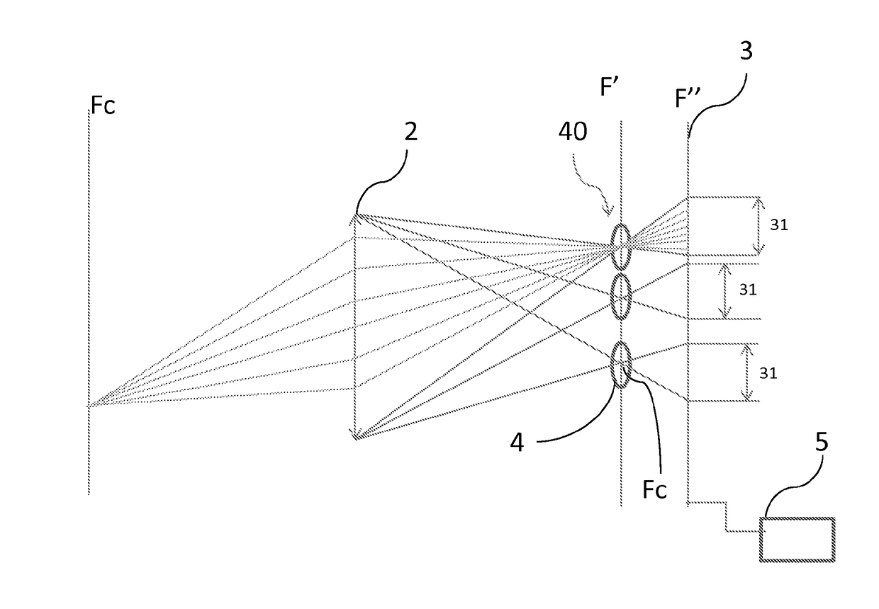
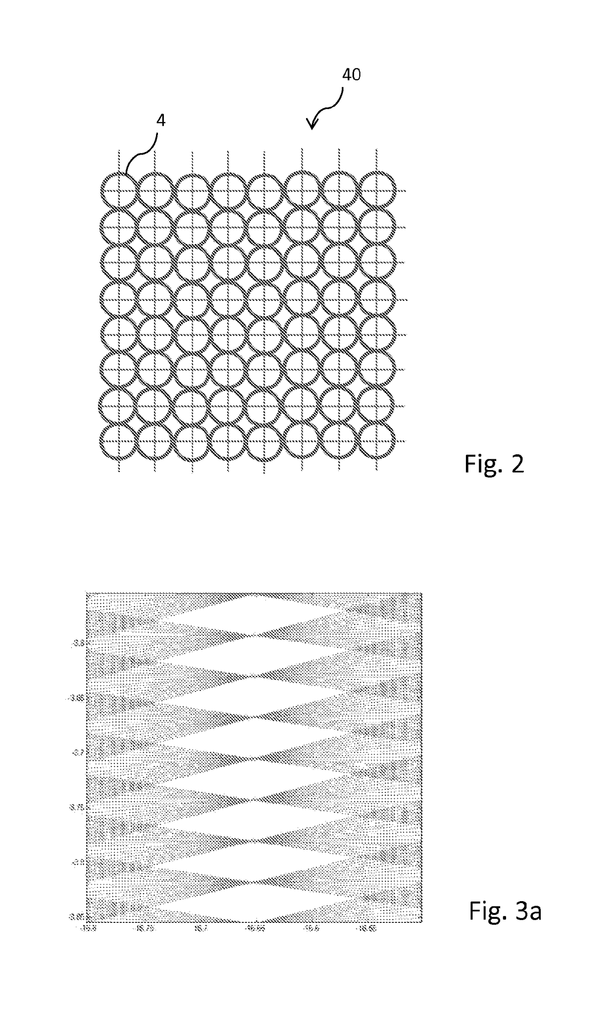
[0076]In a first embodiment, the distance between two adjacent rows is not constant, while the distance between two columns is constant, or alternatively, the distance between two adjacent rows is constant, but the distance between two columns is not constant.

second embodiment

[0077]In a second embodiment, neither the distance between two adjacent rows, nor the distance between two adjacent columns is constant.

[0078]The distance between two adjacent rows and that between two columns is typically less than a millimeter.

[0079]The distance between two adjacent rows and / or that between two adjacent columns is typically selected from a range of values comprised between + and −5% of a mean value.

[0080]Alternatively, the distance between two adjacent rows and / or that between two adjacent columns is typically selected in a range of values comprised between + and −10% of a mean value.

[0081]The distance between two adjacent rows, respectively two columns, is irregular if it is not possible to deduce it from the knowledge of all the other distances between adjacent rows, respectively columns, or if it is necessary to know the distances between at least twenty adjacent rows, respectively twenty columns, to deduce it.

[0082]The distance between two adjacent rows, and / o...


PUM


Abstract

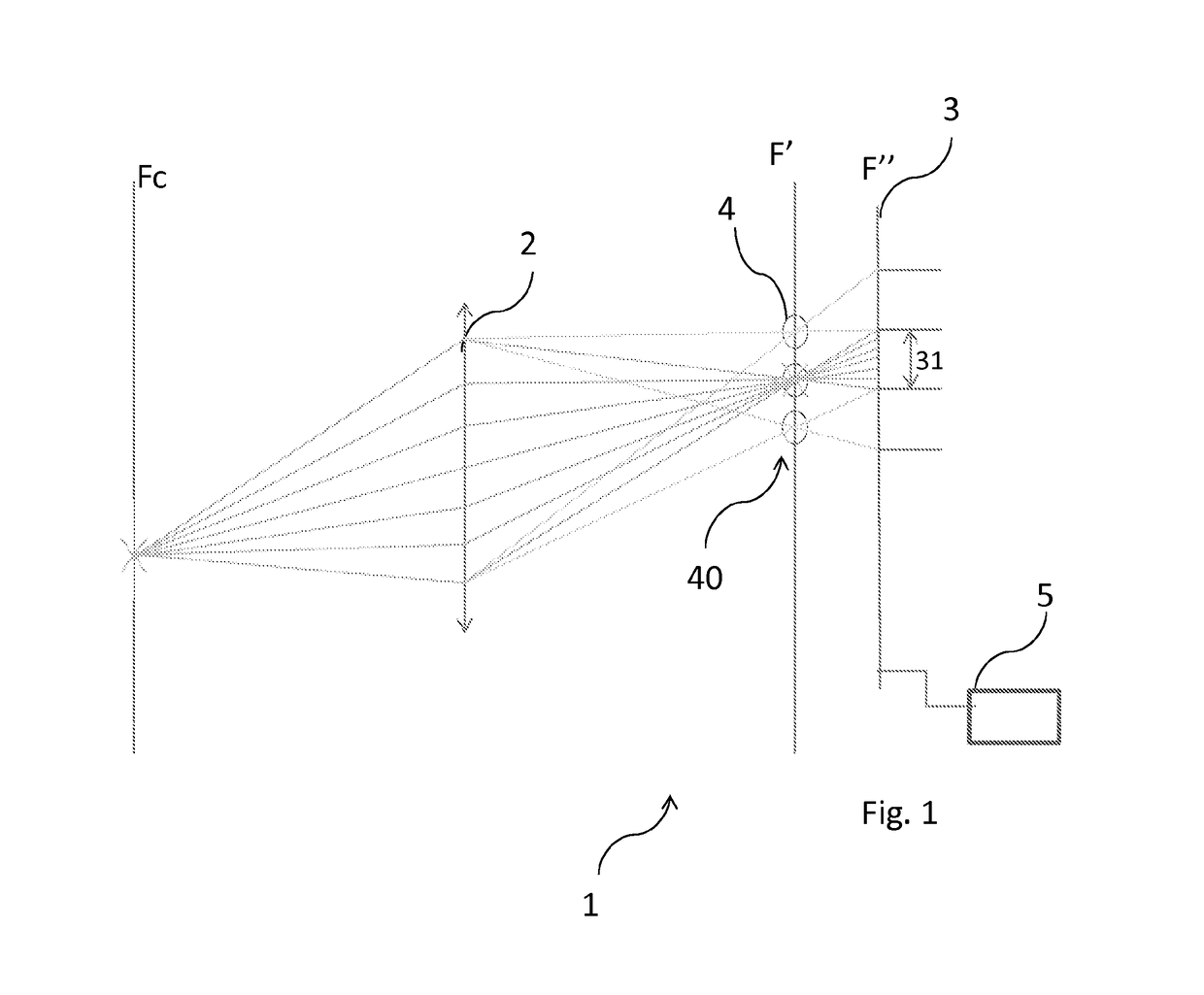
A plenoptic camera including an optical system receiving light issuing from an object field in which there is an object space intended to be processed via the camera. A matrix photosensitive sensor is composed of pixels arranged in rows and columns and such that each pixel receives the light of a single light ray via the system. The light rays, each associated with their pixel, form intersections in the object space, and the optics are configured so as to minimize the greatest distance between any point of the object space and the closest of the intersections of these light rays. Optical elements are aligned and arranged in rows and columns parallel respectively to the rows and columns of the matrix sensor, forming the intersections in the object field, the distances separating the rows and / or columns being irregular.

Description

FIELD OF THE INVENTION[0001]The present invention relates to the field of 3D reconstruction from 2D images, and in particular to plenoptic cameras which allow a 3D scene to be acquired.PRIOR ART[0002]3D reconstruction from 2D images consists of obtaining a representation in three dimensions of an object or a scene from a set of 2D images of the object or of the scene taken from different points of view.[0003]More generally, one or more 2D representations of an object are available and it is desired to determine the coordinates of the elements visible in these representations in a real 3D space frame of reference.[0004]The points visible in the images are the projections of real points which can then be situated on straight rows. If two or more views of the object are taken, the position in space of the real points can then be obtained by intersection of these straight rows (or triangulation).[0005]Using a plenoptic camera 1 to acquire 2D images taken from different points of view of...

Claims


Application Information

Patent Timeline
Patent Type & Authority Applications(United States)
IPC IPC(8): H04N5/225G06T7/557H04N13/246H04N13/232
CPCH04N5/2254G06T7/557H04N5/2256H04N13/246G03B35/08H04N13/232H04N23/957H04N23/672H04N23/56
Inventor LE GUILLOUX, YANNPICARD, SYLVAINE
Owner SAFRAN
Learn More