Gas injection device

a gas injection device and gas technology, applied in the direction of valve operating means/releasing devices, mechanical devices, functional valve types, etc., can solve the problem that the downflow may have a risk of changing and achieve the effect of preventing the change of the property of the wafer contained, facilitating the supply of inert gas, and reliably closing the gas supply por

Active Publication Date: 2018-09-06
SINFONIA TECHNOLOGY CO LTD
View PDF13 Cites 7 Cited by
  • Summary
  • Abstract
  • Description
  • Claims
  • Application Information

AI Technical Summary

Benefits of technology

[0022]In the first aspect, the atmospheric air remaining in the gas passage is preventable from entering into a container to which inert gas is supplied, by opening the gas supply port closed by the opening/closing mechanism after the gas in the gas passage is discharged. Note that, the “atmospheric air” herein may include, but not limited to, oxygen, moisture, and particles that can change the property of wafers contained in the container (e.g., oxygen causes oxidation of wafers contained in the container). Because the entry of the atmospheric air into the container is prevented, it is possible to prevent the change of the property of the wafers contained in the container. Furthermore, the opener causes the opening/closing mechanism to open the closed gas supply port, and this allows inert gas to be easily supplied through the gas supply port.
[0023]In the second aspect, merely by moving the opener upward, the opening/closing mechanism also moves upward, so that the gas supply port closed by the lid portion is opened. Thus, it is possible to easily supply inert gas through the gas supply port.
[0024]In the third aspect, the opener is biased downward by the biasing member, and this allows the lid portion of the opening/closing mechanism fixed to the opener to reliably close the gas supply port. Furthermore, when the opener is moved upward, at an earlier stage of

Problems solved by technology

In some recent cutting-edge processes for wafers, oxygen, moisture, or the like contained in suc

Method used


Image

  • Gas injection device
  • Gas injection device
  • Gas injection device

Examples


Embodiment Construction

[0050]The following describes an embodiment of the present invention with reference to the attached drawings.

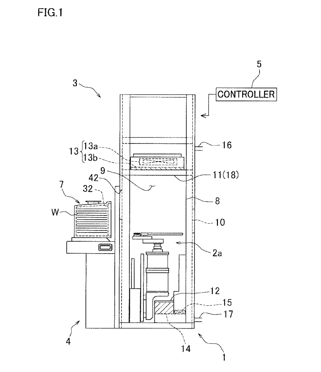
[0051]FIG. 1 is a side view of an equipment front end module (EFEM) 1 from without a side wall so that its inside can be seen. As shown in FIG. 1, the EFEM 1 includes: a wafer conveyance apparatus 2 configured to convey one or more wafers W between predetermined transfer positions; a box-shaped casing 3 provided so as to surround the wafer conveyance apparatus 2; a load port 4 connected to an outer side of a front wall of the casing 3; and a controller 5. In this application, the side of the casing 3 to which the load port 4 is connected is a front side while the side opposite to the front side is a rear side. With respect to the casing 3, the direction toward the load port 4 is defined as a forward direction, and the direction opposite to the forward direction is defined as a rearward direction.

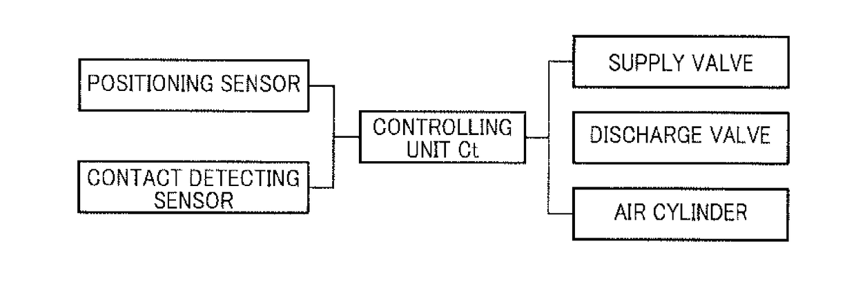
[0052]The controller 5 is configured to control operations of the wafer conveyanc...


PUM


Abstract

There is provided a gas injection device configured to prevent entry of atmospheric air when charging gas into a FOUP. In order to realize such a gas injection device, the gas injection device is structured so as to include: a gas supply port 72 through which inert gas is supplied; a nozzle main body 71 including a gas passage 77 communicating with the gas supply port 72; an opening/closing mechanism 92 configured to close the gas supply port 72; and an opener 96 configured to cause the opening/closing mechanism 92 to open the gas supply port 72 closed by the opening/closing mechanism 92.

Description

TECHNICAL FIELD[0001]The present invention relates to a gas injection device configured to charge nitrogen gas into a container containing wafers being conveyed.BACKGROUND ART[0002]Semiconductors have been produced by conducting various processes to wafers functioning as substrates. In recent years, semiconductor devices are increasingly highly integrated and circuit patterns are becoming increasingly finer. Due to this, there is a demand to maintain the surroundings of wafers highly clean to prevent particles and / or moisture from being attached to surfaces of wafers. Furthermore, to prevent changes of the property of the surfaces of wafers, such as oxidation of the surfaces, arrangements have been made. For example, nitrogen atmosphere (inert gas atmosphere) or a vacuum state is created around the wafers.[0003]In order to properly maintain the atmosphere around the wafers, the wafers are handled in a hermetically-closable storage pod called a front-opening unified pod (“FOUP”). Int...

Claims


Application Information

Patent Timeline
IPC IPC(8): H01L21/673
CPCH01L21/67389H01L21/67393H01L21/67775H01L21/67017F16K31/1221F16K15/147H01L21/67772F16K15/028
Inventor KAWAI, TOSHIHIROTANIYAMA, YASUSHIKOMIYA, MUNEKAZUSHIGETA, TAKASHI
Owner SINFONIA TECHNOLOGY CO LTD
Why Eureka
Try Eureka