
A controller for an inductive load having one or more inductive windings

Active Publication Date: 2018-09-06
INVERTEDPOWER PTY LTD
View PDF9 Cites 34 Cited by
  • Summary
  • Abstract
  • Description
  • Claims
  • Application Information

AI Technical Summary

Benefits of technology

The present invention provides a controller for an inductive load that can overcome or ameliorate the disadvantages of prior art. The controller includes a first input for drawing a DC load current from a first energy source during a first period and for supplying a first DC charging current during a second period. It also includes a second input for drawing a second DC charging current from a second energy source during the second period. The controller includes a switching device that can connect or disconnect the power rails to a common DC energy source or to different energy sources based on the first or second state. The technical effect of the invention is to provide a more flexible and efficient controller for inducing current in an inductive load.

Problems solved by technology

However, the major disadvantage or drawback of electric vehicles remains: the range that is available between recharging is relatively short, and the charging time, particularly to obtain a full charge, is long relative to the refuelling time for a car with an ICE.
This however remains a very expensive infrastructure-based solution that will take considerable time to meaningfully deploy.
The requirement for purpose-built charging stations and other infrastructure to reduce the duration of the recharge time for electric vehicles arises partly from the installation within such vehicles of recharging circuitry that is only capable of accommodating relatively low power levels.
For high power components, and the need to keep those components within acceptable operating temperature ranges, consumes considerable space and adds considerable weight, both of which diminish vehicle performance and range.
Additionally, the weight of the recharging components can be considered dead weight whilst driving, as it is only used when the vehicle is stationary and not operating.
This prior art arrangement is however limited in operation and application.
Moreover, it is not able to gain the benefits of scale, in that where use is made of multiple motors there is also a need to make use of multiple versions of the conversion device.

Method used


Image

  • A controller for an inductive load having one or more inductive windings
  • A controller for an inductive load having one or more inductive windings
  • A controller for an inductive load having one or more inductive windings

Examples


Embodiment Construction

[0102]Described herein is a controller for an inductive load having one or more inductive windings.

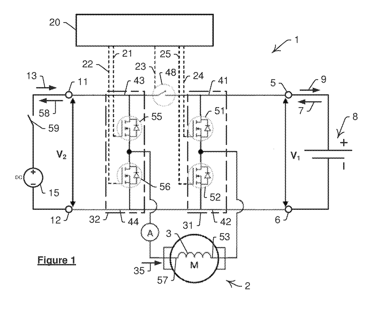
[0103]Referring to FIG. 1 there is illustrated a controller 1 for an inductive load in the form of a DC electric motor 2 which has an inductive winding 3. Controller 1 includes a first input defined by terminals 5 and 6 for drawing a DC load current 7 in a first period from a first energy source in the form of a bank of batteries 8. Terminals 5 and 6 supply a first DC charging current 9 to batteries 8 during a second period. A second input defined by terminals 11 and 12 draws a second DC charging current 13 during the second period from a second energy source in the form of a DC power source 15. A control module 20 issues control signals along control lines 21 to 25, which are illustrated in FIG. 1 as uniformly broken lines. A first drive circuit 31 and a second drive circuit 32, shown bounded in variable broken lines, both operate in a first state and a second state during the first p...


PUM


Abstract

The invention is to a controller for a DC electric motor having a first drive circuit and a second drive circuit that operate in a first state and a second state wherein, in the first state, circuits are connected with terminals input and are responsive to the control signals for receiving a load current and selectively energising winding to create torque in motor. In the second state, circuit is disconnected from terminal such that: circuit is able to be responsive to current for generating a first DC charging current to batteries; and circuit is able to connect with a terminal and be responsive to a second DC charging current for selectively directing an energizing current through winding.

Description

FIELD OF THE INVENTION[0001]The present invention relates to a controller for an inductive load and in particular to a controller for an inductive load having one or more inductive windings.[0002]The invention has been developed primarily for use in plug-in electric vehicles and will be described hereinafter with reference to that application. However, it will be appreciated that the invention is not limited to these particular fields of use and is also applicable to other vehicular uses such as plug-in hybrid electric vehicles whether for private or commercial use. The invention is also applicable to non-vehicle uses such as pumps, compressors, and many other applications of electric motors or inductive loads in many different industries.BACKGROUND[0003]Any discussion of the background art throughout the specification should in no way be considered as an admission that such art is widely known or forms part of common general knowledge in the field.[0004]Electric vehicles have been ...

Claims


Application Information

Patent Timeline
IPC IPC(8): H02P27/08H02P25/22H02J7/14
CPCH02P27/08H02P25/22H02J7/1423B60L11/1803H02J7/022H02J7/345H02P27/06H02J1/10H02J1/12B60L50/51B60L53/24H02J7/02H02J2207/20Y02T90/14Y02T10/7072Y02T10/70Y02T10/64Y02T90/12
Inventor SMOLENAERS, STEFAN
Owner INVERTEDPOWER PTY LTD
Learn More