

Reciprocating compressor for a cooling device
- Summary
- Abstract
- Description
- Claims
- Application Information
AI Technical Summary
Benefits of technology
Problems solved by technology
Method used
Image

Examples
Embodiment Construction
[0024]Referring particularly to such figures, with numeral 100 is denoted the reciprocating compressor according to the invention.
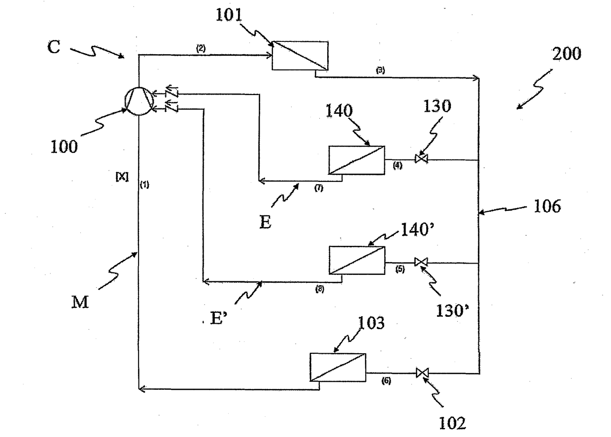
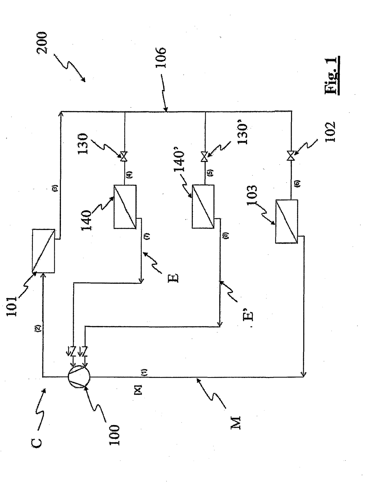
[0025]In FIG. 1 the scheme of a cooling device 200 provided with a reciprocating compressor 100 according to the invention provided with a cylinder 110 and a piston 111 reciprocatingly moving in the cylinder 110, between a top dead centre S (see FIG. 3d) and a bottom dead centre I (see FIG. 3c), is shown. In particular, the refrigeration device 200 comprises a closed circuit C in which a certain flow rate of coolant is circulating. Such a closed circuit C comprises, in its turn, a main branch M, in which a first flow rate X of coolant is circulating and enters the compressor 100 through a suction duct 109, a first secondary branch E and a second secondary branch E′. In such a first secondary branch E a second flow rate X1 of coolant circulates, whereas in the additional secondary branch E′ an additional flow rate X2 of coolant circulates. The sum of the f...
PUM
 Abstract
Description
Claims
Application Information