This helps you quickly interpret patents by identifying the three key elements:
Problems solved by technology
Method used
Benefits of technology
Benefits of technology
The present invention is about an automatic tilting vehicle that reduces energy consumption by calculating the target tilting angle of the vehicle based on the lateral acceleration caused by the gyro moments acting on the wheels. The invention also includes a low pass filterprocessing to prevent sudden changes in the tilting angle and improve ride comfort, or quickly change the target tilting angle to ensure good turning performance, depending on the vehicle's speed and steering operation amount.
Problems solved by technology
Therefore, it is difficult to precisely control a tilt angle of the vehicle with good response so that the tilt angle of the vehicle conforms to a target tilt angle.
Therefore, a range of the vertical movement of each tie rod is limited to a narrow range and, accordingly, an angular range capable of tilting the vehicle is limited.
In an automatic tilting vehicle, particularly an improved automatic tilting vehicle having a large tiltable angular range, as described below, there is a problem that an energy consumed by the actuator is large and a tilt angle of the vehicle cannot necessarily be precisely controlled to the target tilt angle.
Therefore, since a deviation between a target lateral acceleration and the actual lateral acceleration of the vehicle becomes large, even if the vehicle tilting device is controlled so that the tilt angle of the vehicle becomes a target tilt angle, it is difficult to accurately control the tilt angle of the vehicle to the target tilt angle.
Further, when the positional relationship between the swing member and the pair of tie rods changes, elastic deformation amounts of elastic members elastically urging the swing member and the pair of tie rods to their positions in the standard state of the vehicle change from the original values that are elastic deformation amounts when the positional relationship does not change, which causes to accumulate energy.
Therefore, even if the vehicle tilting device is controlled so that the tilt angle of the vehicle becomes a target tilt angle, it is difficult to accurately control the tilt angle of the vehicle to the target tilt angle.
The reason why an energy consumed by the actuator is large and it is difficult to accurately control the tilt angle of the vehicle to the target tilt angle is the fact that a lateral acceleration of the vehicle caused by the gyro moments are not taken into account when calculating a target tilt angle of the vehicle.
Method used
Image
Click on the blue label to locate the original text in one second.
Reading with bidirectional positioning of images and text.
Examples
first embodiment
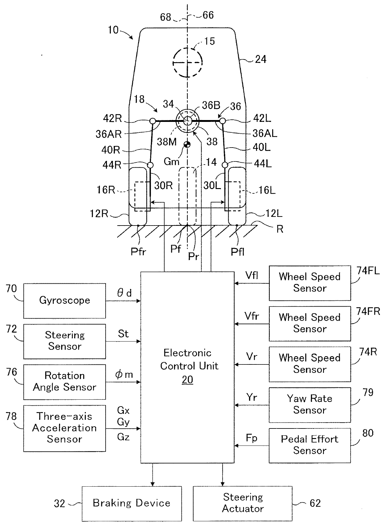
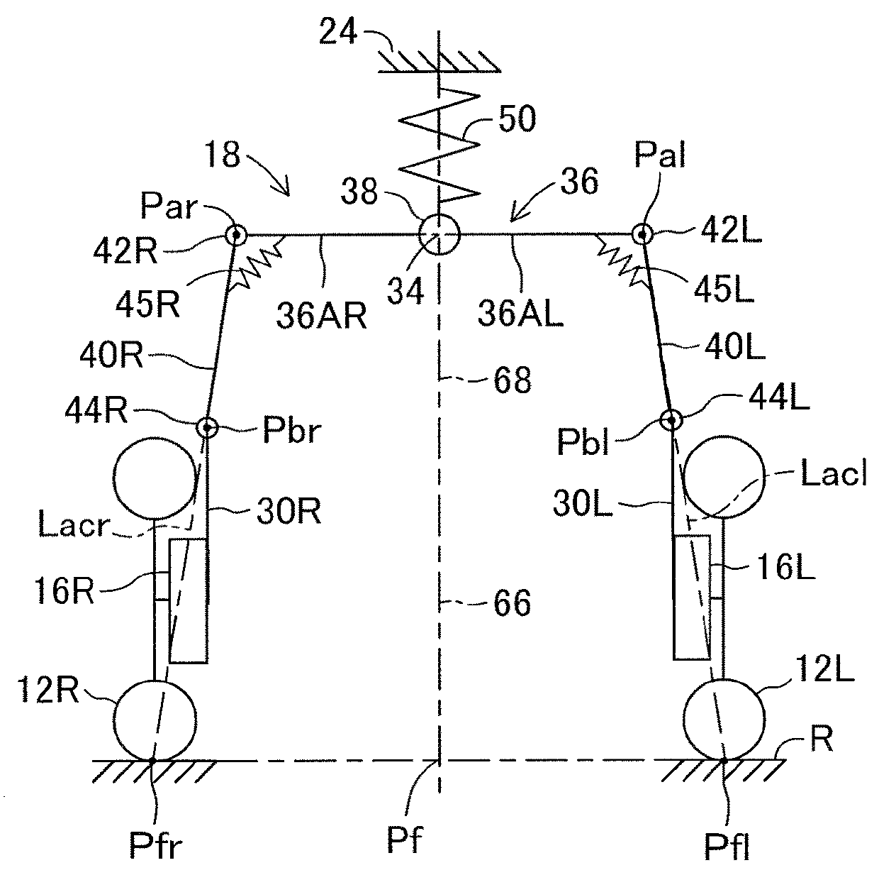
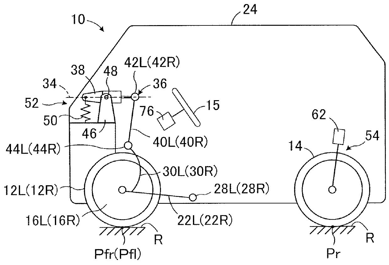
[0050]In FIGS. 1 to 4, an automatic tilting vehicle 10 according to an embodiment of the present disclosure is a tricycle vehicle with a capacity of one which includes a pair of front wheels 12L and 12R that are non-steered drive wheels, and a rear wheel 14 that is a steered driven wheel. The front wheels 12L and 12R are spaced apart from each other in the lateral direction and are rotatably supported about a rotation axis (not shown) by corresponding knuckles (wheel carriers) 16L and 16R.
[0051]In the embodiment, a camber of the front wheels 12L and 12R is a neutral camber, so that a camber angle of the front wheels at the time when the vehicle 10 is not turning. It should be noted that the camber of the front wheels may be a negative camber or may be a positive camber. The rear wheel 14 is located rearward of the front wheels and steered in a steer-by-wire manner according to an amount of operation of a steering wheel 15 by a driver, as will be described in detail later. In FIG. 1 ...
second embodiment
[0137]FIG. 18 is a flowchart showing a control routine for controlling the tilt angle of the vehicle according to the second embodiment of the automatic inclined vehicle according to the present invention. In FIG. 18, the same step numbers as those shown in FIG. 7 are assigned to the same steps as those shown in FIG. 7. Further, the configuration of the second embodiment relating to the control routine of the tilt angle of the vehicle and the control routine of the steered angle of the rear wheel is the same as that of the first embodiment.
[0138]As can be understood from the comparison between FIG. 18 and FIG. 7, in the second embodiment, step 90 in the first embodiment is not executed, and upon completion of step 80, the control of the tilt angle proceeds to step 100. Therefore, since the magnitude of the target tilt angle θt of the vehicle is not limited, the magnitude of the target tilt angle θt may become larger than the maximum allowable tilt angle θamax.
[0139]In the second emb...
third embodiment
[0143]FIG. 19 is a schematic configuration diagram showing a third embodiment of the automatic inclined vehicle according to the present invention. In FIG. 19, the same reference numerals as those denoted in FIG. 1 are given to the same members as those shown in FIG. 1.
[0144]As can be understood from the comparison between FIG. 19 and FIG. 1, in the third embodiment, the vehicle 10 is provided with a setting switch 81 operated by the occupant, and the setting switch 81 functions as a setting device for setting whether or not to limit a magnitude of the target tilt angle θt of the vehicle. This switch is switched between on and off, and when it is on, it is set to limit the magnitude of the target tilt angle θt.
[0145]In the third embodiment, when the setting switch 81 is on, a tilt angle θ of the vehicle 10 and a steered angle δr of the rear wheel 14 are controlled in the same manner as in the above-described first embodiment. On the other hand, when the setting switch 81 is off, a t...
PUM
Abstract
An automatic tilting vehicle is provided that includes left and right front wheels supported by knuckles, a steerable rear wheel, a vehicle tilting device, and a control unit. The vehicle tilting device includes a swing member, a tilt actuator for swing the swing member, and a pair of tie rods pivotally attached to the swing member and the knuckles. The control unit calculates a target lateral acceleration of the vehicle, estimates a lateral acceleration of the vehicle caused by the gyro moments of the wheels and calculates a target tilt angle of the vehicle based on a sum of the target lateral acceleration and the lateral acceleration caused by the gyro moments.
Description
CROSS-REFERENCE TO RELATED APPLICATION[0001]The disclosure of Japanese Patent Application NO. JP2017-53346 filed on Mar. 17, 2017 is incorporated by reference in its entirety.BACKGROUND1. Technical Field[0002]The present disclosure relates to an automatic tilting vehicle that automatically tilts (self inclines) to the inside of a turn when turning.2. Description of the Related Art[0003]An automatic tilting vehicle has a vehicle tilting device, and the vehicle is automatically tilted to the inner side of a turn by the vehicle tilting device at the time of turning. For example, International Publication No. 2012 / 049724 describes an automatic tilting vehicle that includes a pair of front wheels spaced laterally, a swing type vehicle tilting device, and a control unit that controls the vehicle tilting device, and the pair of front wheels are rotatably supported by corresponding knuckles. The vehicle tilting device includes a swing member swingable about a swing axis extending in a longi...
Claims
Application Information
Patent Timeline
Application Date:The date an application was filed.
Publication Date:The date a patent or application was officially published.
First Publication Date:The earliest publication date of a patent with the same application number.
Issue Date:Publication date of the patent grant document.
PCT Entry Date:The Entry date of PCT National Phase.
Estimated Expiry Date:The statutory expiry date of a patent right according to the Patent Law, and it is the longest term of protection that the patent right can achieve without the termination of the patent right due to other reasons(Term extension factor has been taken into account ).
Invalid Date:Actual expiry date is based on effective date or publication date of legal transaction data of invalid patent.

