Control device for transport vehicle

a technology for controlling devices and transport vehicles, applied in the direction of electric devices, transportation and packaging, propulsion using engine-driven generators, etc., can solve the problems of frequent and immediate output limits, prevent unnecessary threshold value setting, and delay the effect of temperature rise of electric motors or electric devices

Active Publication Date: 2018-09-20
HONDA MOTOR CO LTD
View PDF0 Cites 0 Cited by
  • Summary
  • Abstract
  • Description
  • Claims
  • Application Information

AI Technical Summary

Benefits of technology

[0014]When the electric motor is in the stalled state and the required driving force is less than the second predetermined value, there is a high possibility that the transport vehicle is stopped with a balance of the driving force on the uphill road. Therefore, according to the second aspect, the value to be set when the required driving force is less than the second predetermined value is set lower than the value to be set when the required driving value is equal to or larger than the second predetermined value, and thus it is possible to suppress overheating due to the output limit corresponding to the low threshold value when the required driving force is less than the second predetermined value and to perform the output limit the electric motor according to a high threshold value when the required driving force increases from this state to the second predetermined value or more. Therefore, the electric motor can operate without the output limit immediately after the required driving force increases.
[0015]In the transport vehicle, no overloading occurs unless one phase concentration does not occur in the electric motor, which is a polyphase electric motor, or the electric device for driving the electric motor. According to the third aspect, the threshold value is set to the variable value only when the condition that the parameter relating to the traveling speed of the transport vehicle is less than the upper limit value at which one phase concentration can occur in the electric motor or the electric device for driving the electric motor is satisfied, the unnecessary setting change of the threshold value can be prevented.
[0016]The parameter relating to the electric motor or the electric device is proportional to the square of the current flowing therethrough, and the current is proportional to the torque of the electric motor. Therefore, according to the fourth aspect, the torque of the electric motor is limited when the required driving force is equal to or larger than the third predetermined value and less than the second predetermined value, and thus the temperature rise of the electric motor or the electric device can be delayed.
[0017]Since the intention of the driver to accelerate is strong when the required driving force is equal to or larger than the second predetermined value, as in the invention according to the fifth aspect, the threshold value is set to the maximum value, whereby the frequent output limit of the electric motor can be prevented.

Problems solved by technology

As a result, there is a high possibility that the output limit is frequently performed immediately after the required driving force of the electric motor being in the stalled state increases.

Method used


Image

  • Control device for transport vehicle
  • Control device for transport vehicle
  • Control device for transport vehicle

Examples


Embodiment Construction

[0029]A hybrid electric vehicle (HEV) mounted with a control device according to an embodiment of the invention will be described below with reference to the drawings.

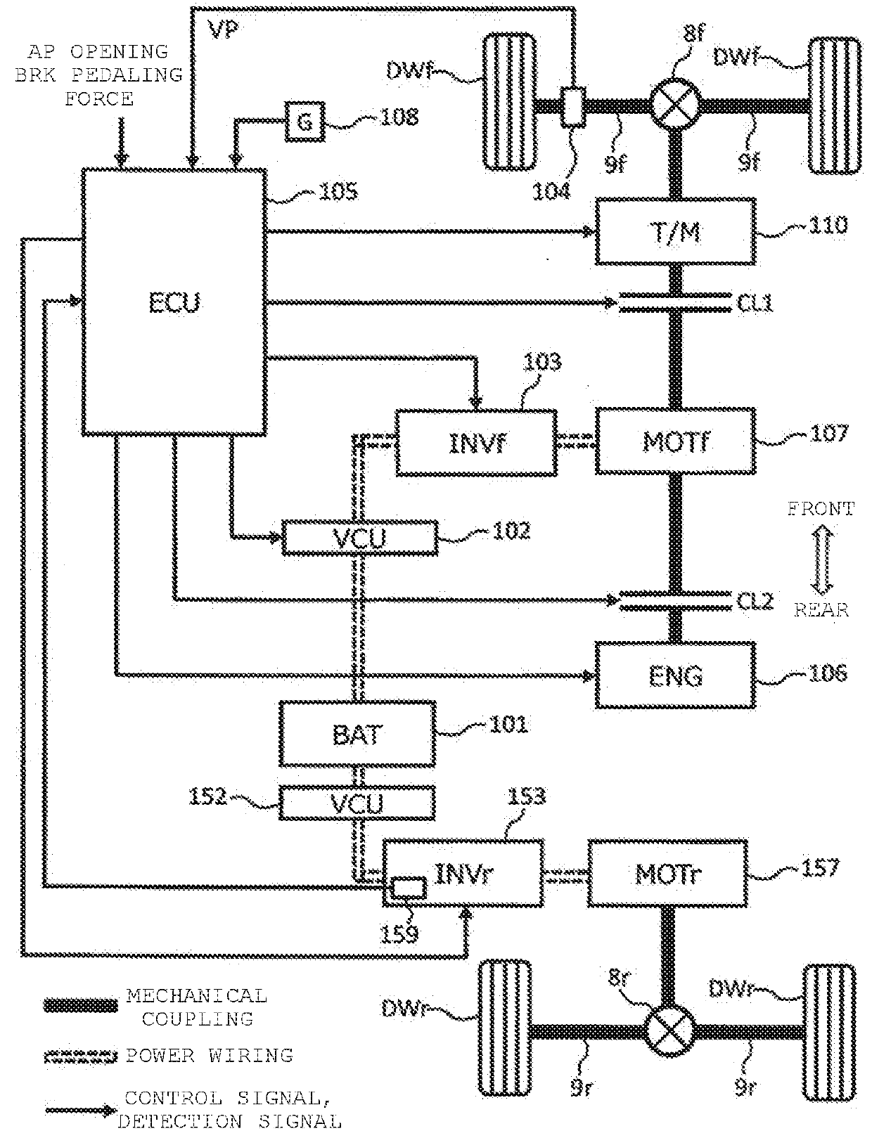
[0030]FIG. 1 is a block diagram illustrating an internal configuration of the hybrid electric vehicle according to the embodiment. The hybrid electric vehicle (hereinafter, simply referred to as a “vehicle”) illustrated in FIG. 1 includes an internal combustion engine (ENG) 106, an electric motor (MOTf) 107, a transmission (T / M) 110, a connecting / disconnecting unit CL1, a connecting / disconnecting unit CL2, a battery (BAT), 101, a VCU (Voltage Control Unit) 102, an inverter (INVf) 103, a speed sensor 104, an acceleration sensor 108, an electric motor (MOTr) 157, a VCU (Voltage Control Unit) 152, an inverter (INVr) 153, a temperature sensor 159, and an ECU (Electronic Control Unit) 105. The vehicle travels with power of the internal combustion engine 106 and / or the electric motors 107 and 157 according to traveling condi...


PUM


Abstract

A control device for a transport vehicle configured to travel with a driving force output from an electric motor is provided. When the transport vehicle is driven by a driving force of the electric motor and a variation rate is equal to or less than a predetermined value while a parameter relating to a traveling speed of the transport vehicle is less than a first predetermined value, the control device sets a threshold value, at which an output limit of the electric motor is started based on a parameter relating to a temperature of the electric motor or a temperature of an electric device for driving the electric motor, to a variable value corresponding to a required driving force to the transport

Description

CROSS-REFERENCE TO RELATED APPLICATION[0001]The present application claims the benefit of priority of Japanese Patent Application No. 2017-052173, filed on Mar. 17, 2017, the content of which is incorporated herein by reference.BACKGROUND1. Field of the Invention[0002]The present invention relates to a control device for a transport vehicle that can travels with a driving force output from an electric motor.2. Description of the Related Art[0003]In a control device for a vehicle disclosed in JP-A-2013-49368, since an accelerator pedal is depressed with a substantially constant operation amount on an uphill road, when it is determined that the vehicle is in a “stalled state” being stopped in a state in which an output torque is transmitted to driving wheels from an electric motor, a motor torque instruction value is generated so that the output torque of the electric motor decreases and a brake torque instruction value is generated so that a braking power of a brake unit is increased...

Claims


Application Information

Patent Timeline
Patent Type & Authority Applications(United States)
IPC IPC(8): B60L3/06B60L15/20B60L50/16
CPCB60L3/06B60L15/2027B60L15/2072B60W10/08B60W20/00B60W40/105B60L15/2081B60L2240/12B60L2240/423B60L2240/425B60L2240/525Y02T10/64Y02T10/72Y02T10/62Y02T10/7072
Inventor MATSUO, YUHEI
Owner HONDA MOTOR CO LTD
Why Eureka
Try Eureka