Ignition system and spark plug

a technology of ignition system and spark plug, which is applied in the direction of sparking plug, sparking device, machine/engine, etc., can solve the problems of inability to efficiently apply energy to the spark, spark is not generated, and is likely to occur, so as to improve ignitability, shorten the period, and excellent ignitability

Inactive Publication Date: 2015-03-10
NGK SPARK PLUG CO LTD
View PDF19 Cites 0 Cited by
  • Summary
  • Abstract
  • Description
  • Claims
  • Application Information

AI Technical Summary

Benefits of technology

[0021]According to the above configuration 1, it is configured such that both the voltage from the discharge power supply and the AC power from the AC power supply pass through the electrode (in other words, pass through the same line) to be supplied to the gap. Therefore, the AC power is applied directly to a spark, not through a space or the like, and energy can be applied to the spark efficiently. As a result, the plasma to be generated by applying AC power to the spark can be made larger, and ignitability can be dramatically improved.
[0071]According to the above configuration 13, the thermal conduction path from the tip end portion of the ground electrode to the metal shell is shortened, and thus the heat of the ground electrode can be more smoothly conducted to the metal shell side. As a result, it is possible to suppress the overheating of the ground electrode, and still further improve the wear resistance of the ground electrode.

Problems solved by technology

However, a spark is generated only by high frequency power in the above technology.
Therefore, even if high frequency power is applied, a situation where a spark is not generated (what is called a misfire) is likely to occur.
In the technology described in JP-A-2009-38026, however, since an electromagnetic wave is transmitted to a spark (plasma) through a space in the technology described in JP-A-2009-38026, an efficient application of energy to the spark cannot be performed and the effect of an improvement in ignitability is therefore small.
Moreover, efficient radiation of an electromagnetic wave requires minute adjustments of the size of the antenna, and the like in consideration of factors, such as the wavelength, frequency, and the like of the electromagnetic waves, which may lead to an increase in manufacturing costs.

Method used


Image

  • Ignition system and spark plug
  • Ignition system and spark plug
  • Ignition system and spark plug

Examples


first embodiment

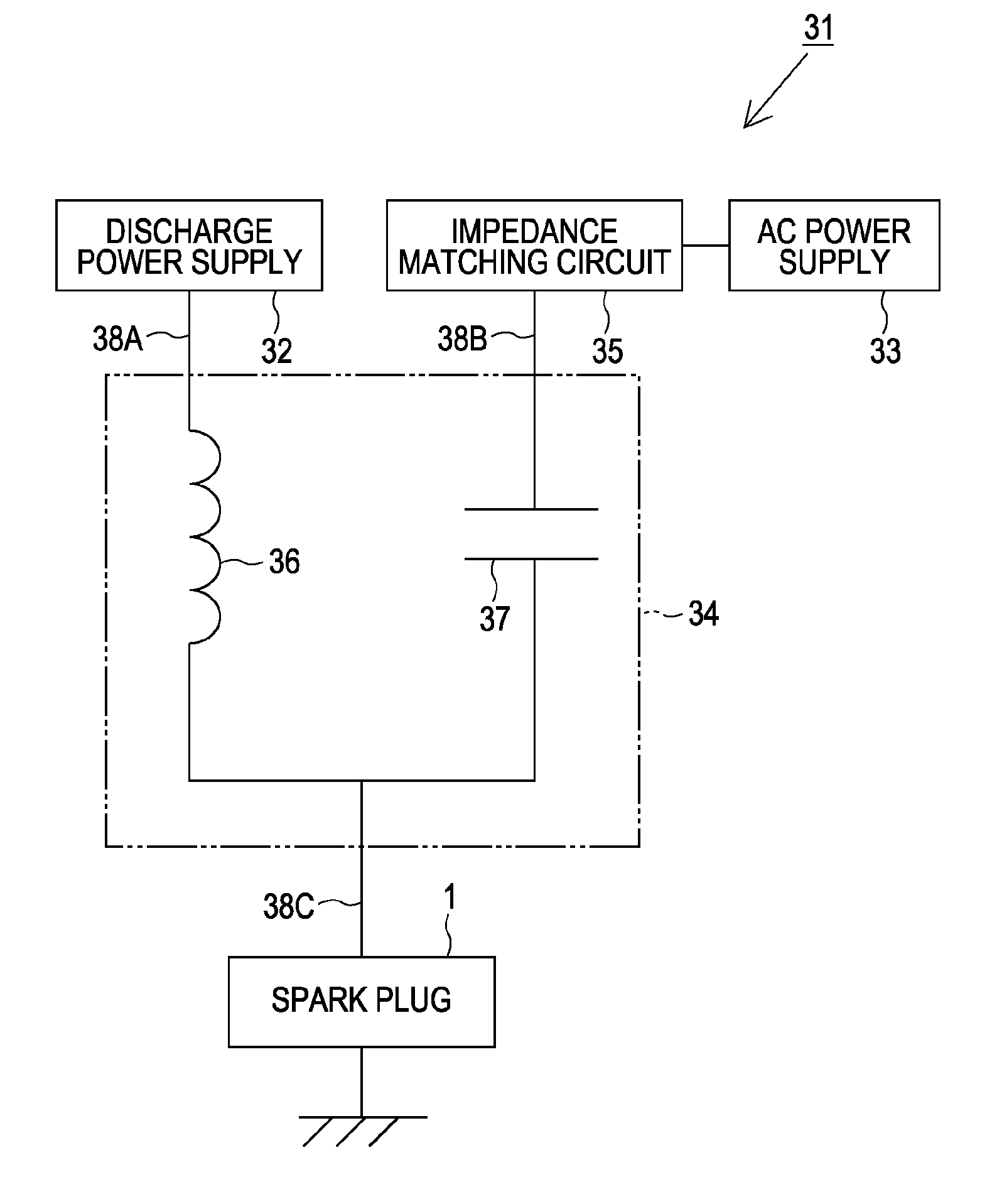
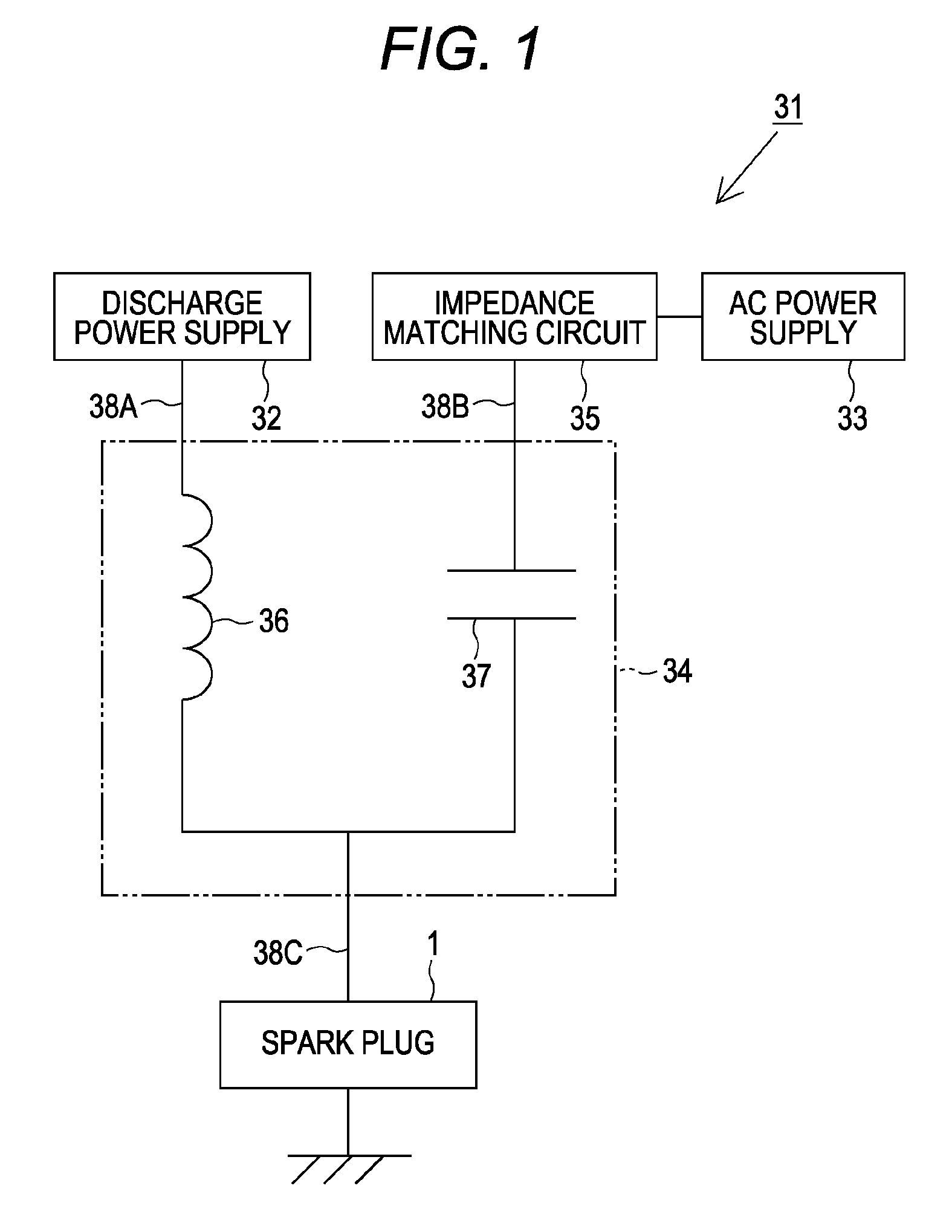
[0098]FIG. 1 is a block diagram illustrating the schematic configuration of an ignition system 31. In FIG. 1, only one spark plug 1 is illustrated. However, a plurality of cylinders is provided in an actual combustion apparatus, and the spark plug 1 is provided to each cylinder. Power from a discharge power supply 32 and an AC power supply 33, which are described below, is supplied to the spark plugs 1 via a distributor (not illustrated).

[0099]The ignition system 31 includes the spark plug 1, the discharge power supply 32, the AC power supply 33, and a mixed circuit 34.

[0100]The discharge power supply 32 is for supplying high voltage to the spark plug 1, and generating a spark discharge in a spark discharge gap 28 to be described below. As the discharge power supply 32, for example, an ignition coil can be used.

[0101]The AC power supply 33 is for supplying AC power to the spark plug 1. Moreover, an impedance matching circuit 35 is provided between the AC power supply 33 and the mixe...

second embodiment

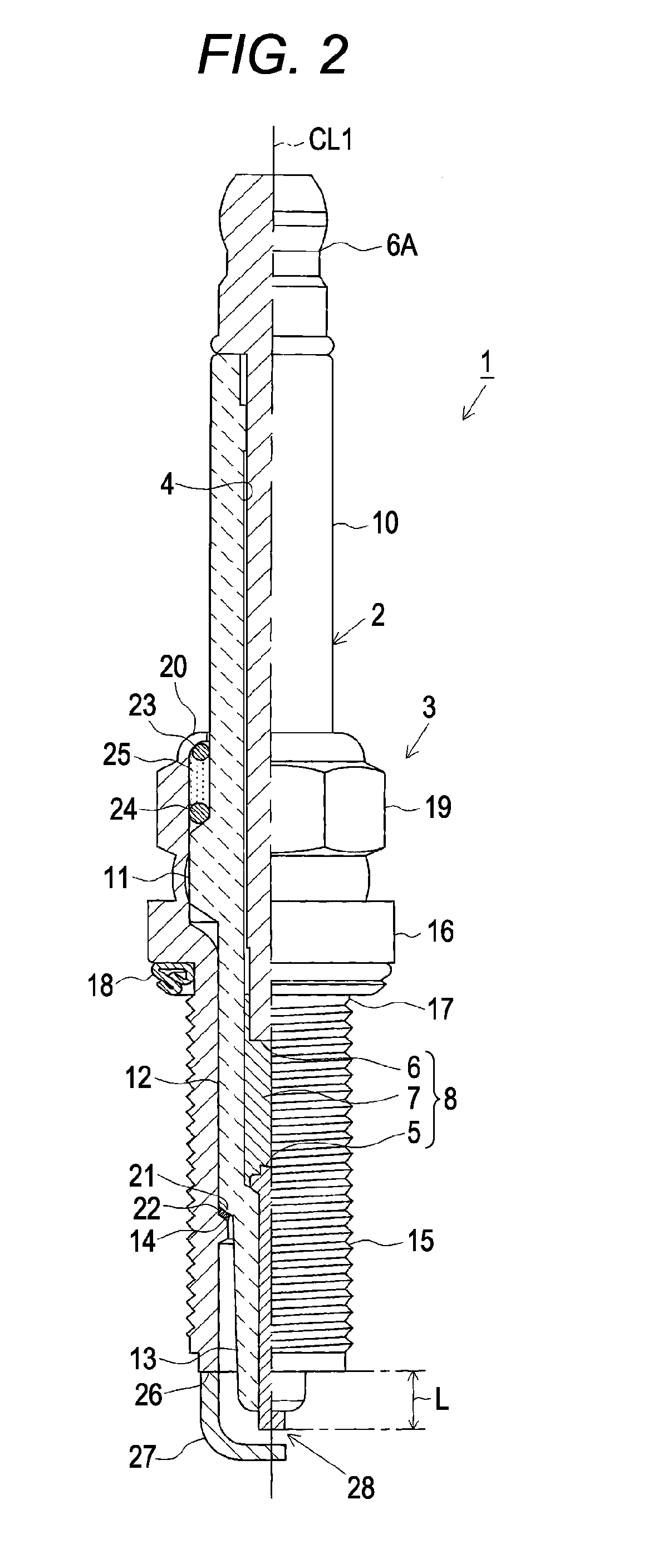
[0146]Next, a description will be given of a second embodiment. In the second embodiment, especially the configuration of the spark plug 1 is different from that of the above first embodiment. Accordingly, a description will be given of the configuration of the spark plug 1.

[0147]As illustrated in FIGS. 7 and 8, in the embodiment, the total volume of portions of the electrode 8, the ground electrode 27, and the insulator 2, the portions being located in an area with a radius of 2.5 mm from the center CP of the spark discharge gap 28, is set to 20 mm3 or less. Moreover, in the embodiment, the size of the spark discharge gap 28 (the length of a line segment LS to be described below) is made relatively large (e.g., 0.5 mm or more), and it is configured such that the electrode 8 and the ground electrode 27 are relatively away from the center CP. Further, the shortest distance from the tip end of the metal shell 3 to the center CP of the spark discharge gap 28 is set to 2.5 mm or more, a...


PUM


Abstract

An ignition system having a spark plug, a discharge power supply, and an AC power supply. Voltage from the discharge power supply and AC power from the AC power supply are supplied to a spark discharge gap through an electrode of the spark plug. The AC power from the AC power supply is applied to a spark generated by the voltage from the discharge power supply in the spark discharge gap.

Description

FIELD OF THE INVENTION[0001]The present invention relates to an ignition system and a spark plug, which are used for an internal combustion engine or the like.BACKGROUND OF THE INVENTION[0002]A spark plug used for a combustion apparatus such as an internal combustion engine includes, for example, a center electrode extending in an axis direction thereof, an insulator provided on a periphery of the center electrode, a tubular metallic shell assembled to the outside of the insulator, and a ground electrode having a proximal end portion joined to a tip end portion of the metal shell. When high voltage is applied to the center electrode, a spark is generated in a gap formed between the center electrode and the ground electrode. As a result, fuel gas is ignited.[0003]In recent years, there has been known a technology for generating a spark by applying AC power (high frequency power) to the gap instead of high voltage to promote an improvement in ignitability (see, for example, JP-A-2009-...

Claims


Application Information

Patent Timeline
Patent Type & Authority Patents(United States)
IPC IPC(8): F23Q3/00F02P3/01F02P9/00H01T13/40H01T13/50
CPCF02P3/01H01T13/40H01T13/50F02P9/007F02P3/00H01T13/20
Inventor KATSURAYA, KOHEINAKAYAMA, KATSUTOSHI
Owner NGK SPARK PLUG CO LTD
Why Eureka
Try Eureka