Overheat protection circuit and method in an accelerated aging test of an integrated circuit

a technology of overheating protection and integrated circuit, which is applied in the direction of measurement devices, digital storage, instruments, etc., can solve the problems of many integrated circuits, or ics, experiencing degradation, repeated current consumption, and heating of the device, so as to reduce the possibility of overheating damage, the effect of reducing or non-existent, and efficient and reliabl

Active Publication Date: 2019-08-06
MICRON TECH INC
View PDF9 Cites 1 Cited by
  • Summary
  • Abstract
  • Description
  • Claims
  • Application Information

AI Technical Summary

Benefits of technology

[0011]In accordance with at least one aspect of the claimed subject matter, an IC chip and any device including the same may undergo an efficient and reliable accelerated aging test with reduced, or non-existent, possibility of suffering the overheat-damages.
[0012]In accordance with at least one aspect of the claimed subject matter, an IC chip and any device including the same that undergo an accelerated aging test can automatically suppress overheating of the IC chip, if the operating temperature reaches a certain predetermined level.
[0013]In accordance with at least one aspect of the claimed subject matter, an IC chip and any device including the same may undergo an accelerated aging test, where the aging conditions are automatically adjusted so as to prevent the overheating of the chip.

Problems solved by technology

Many integrated circuits, or ICs, experience degradation over time due to aging of the underlying transistors.
Causes of this aging may include a repeated current consumption, leakage current production, heating of the device (due to high temperature), and / or physical degradation of parts due to passage of time.
Various aging effects cause continuous performance and reliability degradation during circuit run-time usage.
By performing such an accelerated aging test on an IC chip, it can be known whether any part of the chip produces too much leakage current, is incapable of dissipating power or current, or is heated up too much to cause overheat damages to adjacent parts, and / or is vulnerable to any of the aging conditions.
The aggravated conditions used in the accelerated aging test, such as a higher than normal operating voltage, however, often lead to an increased amount of leakage current on the tested IC chip, which can overheat the chip.
Such an overheating of the chip may cause various malfunctioning damages to the chip and the tester device as well.
Although the chip may recover from the overheat damages when it is allowed to cool, it is not always the case.
Sometimes, the overheat damages may be permanent and not reversible.
Furthermore, such overheat damages can be done not only to the overheated chip but also to the tester device as well.
Due to these overheat problems, an accelerated aging test has been limited to such an extent that the testing aging conditions are controlled so as not to cause the overheat problems in the tested chip and the tester device.
Specifically, more alleviated aging conditions are chosen to prevent the overheat damages, and these conditions are often insufficient to simulate a proper aging of the tested IC chip to appropriately judge the chip's overall reliability and performance, including the vulnerability / resistibility to the long-term effects of the aging conditions.
This often reduces the efficiency of the accelerated aging test.
That means that the devices should be left for several years or they do aging.
Depending in transistor characteristics, some devices will run into a vicious circle that leads to their destruction.
High temperature causes to increase currents / current densities inside the device.
Increased current consumption will heat up the device more than the elevated temperature in the “burn oven”.
If the local device heats up higher, its current consumption gets higher and so forth.
Eventually the device melts and also might destroy the test equipment that it is tested with.
This problem provides the damage to the test system.

Method used


Image

  • Overheat protection circuit and method in an accelerated aging test of an integrated circuit
  • Overheat protection circuit and method in an accelerated aging test of an integrated circuit
  • Overheat protection circuit and method in an accelerated aging test of an integrated circuit

Examples


first embodiment

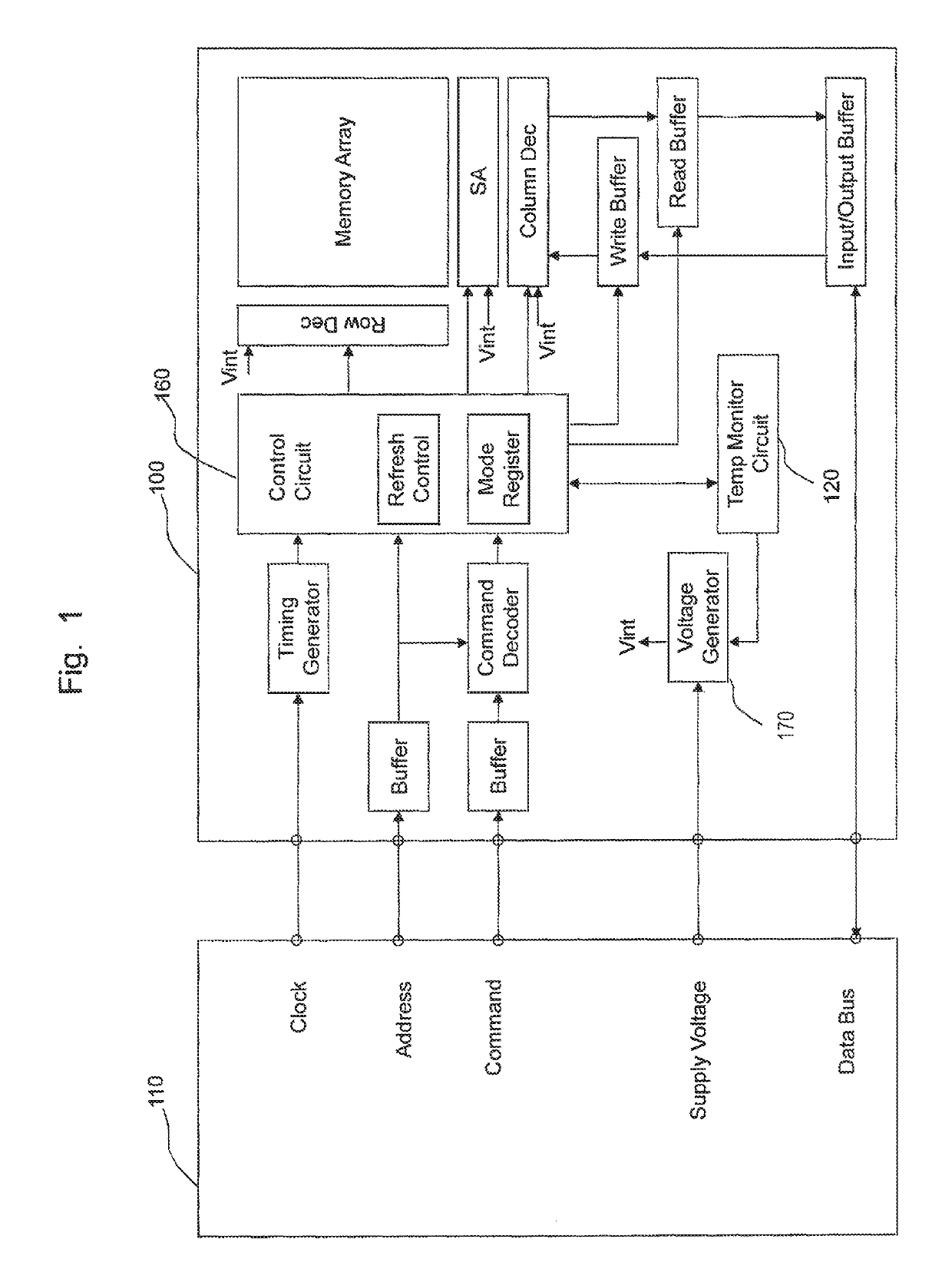
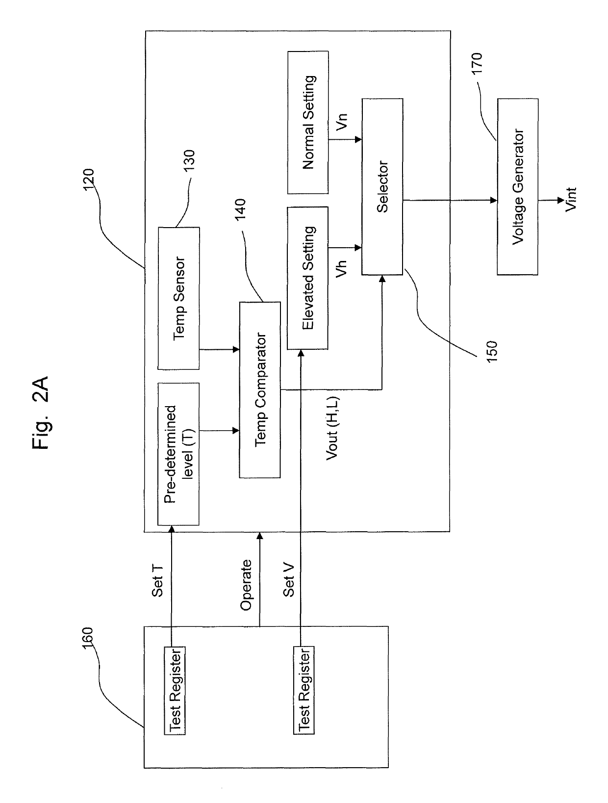
[0045]FIG. 2A is a block diagram showing an example of a configuration of a temperature monitor circuit 120 and a control circuit 160 according to a In FIG. 2, the control circuit 160 sets a predetermined temperature level T (e.g., overheat trigger point) as well as a testing voltage level V. This testing voltage level may include either or both the elevated voltage level, Vh, and the normal voltage level, Vn. Further, either or both these values may be input from the tester device 110 and fed into the control circuit of the memory device, or may be pre-set in the memory device 100. The elevated voltage level, Vh, is higher than the normal voltage level, Vn.

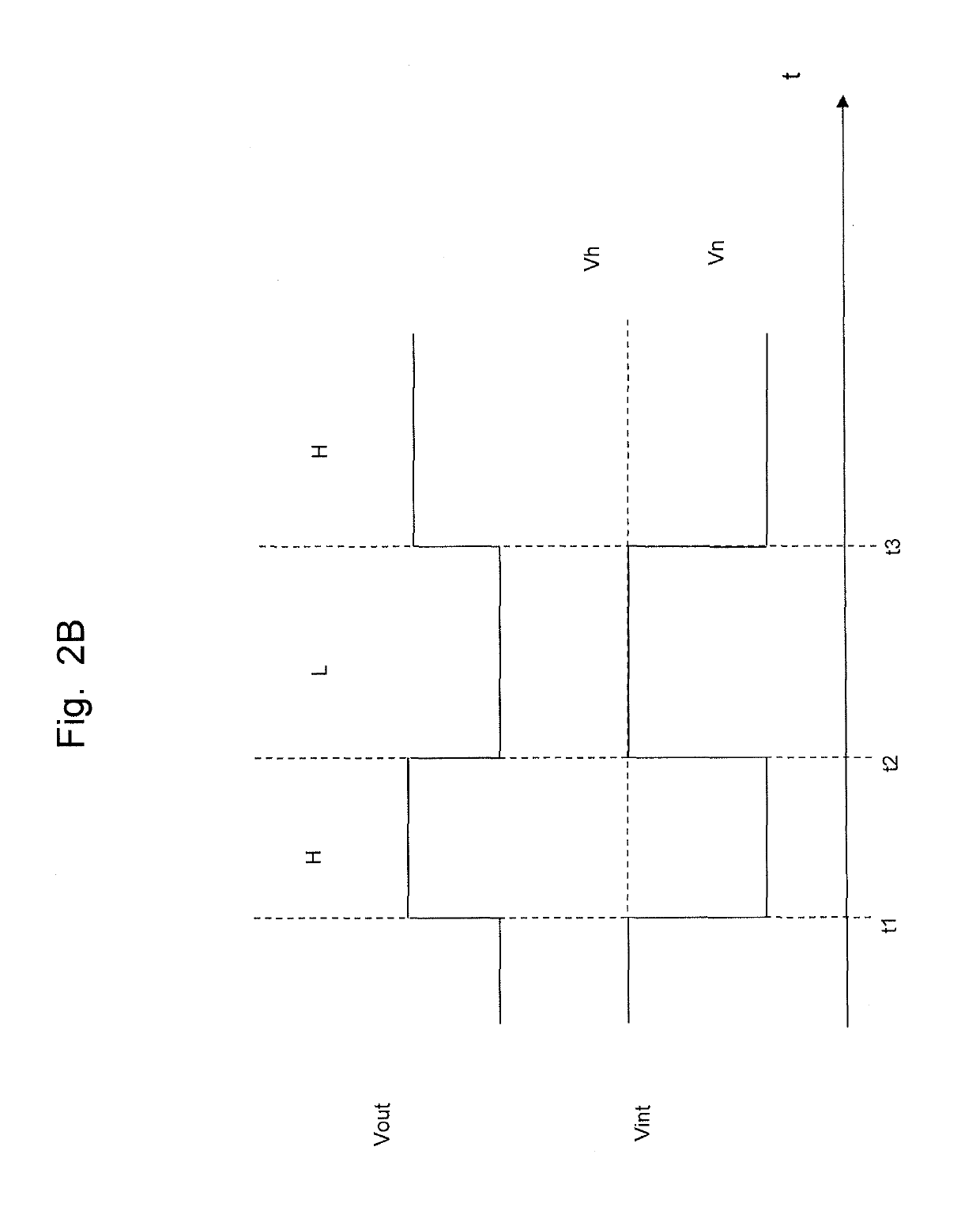
[0046]The predetermined temperature T is the temperature trigger point such that if the operating temperature of the memory device 100 reaches this predetermined temperature level T, the memory device changes its operating conditions to be in a reduced-current-consumption state to ultimately lower the operating temperature.

[0047...

second embodiment

[0060]FIG. 3A is a block diagram showing an example of a configuration of a temperature monitor circuit 320 and a control circuit 360 according to a A circuit configuration and an operation of the temperature monitor circuit 320 and control circuit 360 are similar to the circuit configuration and the operation of the temperature monitor circuit 120 and control circuit 160, shown in FIG. 2A, and thus redundant explanations thereof will be omitted.

[0061]In FIG. 3A, the elevated voltage has three different voltage levels, V1, V2, and V3. V1 is highest voltage of all three, and V2 is a middle value, and V3 is the lowest voltage. The normal voltage setting remains to be Vn, and is lower than the lowest elevated voltage, V3. There is provided a gate and a timer to control transferring of signals of the path from the output of the temp comparator 340 to the selector 350. The gate is controlled by the timer, to control the timing, period, and / or frequency of the selection process of the se...

third embodiment

[0076]FIG. 4 is a block diagram showing an example of a configuration of a voltage generator according to a In this example, the voltage generator is configured to stop producing the voltage, thereby completely turning off the memory device 400, when the temperature of the memory device 400 reaches the overheat trigger point T.


PUM


Abstract

To include in a device a controller to control operation of the device in a normal-operation mode and in a test mode for performing one or more tests including an accelerated aging test, a temperature sensor to measure operating temperature of the device, and an overheat protection circuit to prevent overheating of the memory device during the test mode. With this overheat protection circuit, a device may undergo an efficient and reliable accelerated aging test with reduced or non-existent, possibility of suffering an overheat damage.

Description

BACKGROUND[0001]Field[0002]The present disclosure relates to an integrated circuit (IC) and an information processing device including the same, and more particularly relates to an accelerated aging test of an integrated circuit device and an information processing device including the same.[0003]Description of the Related Art[0004]Many integrated circuits, or ICs, experience degradation over time due to aging of the underlying transistors. Causes of this aging may include a repeated current consumption, leakage current production, heating of the device (due to high temperature), and / or physical degradation of parts due to passage of time.[0005]Various aging effects cause continuous performance and reliability degradation during circuit run-time usage. Thus, in order to ensure the lifetime circuit reliability, an IC chip usually goes through what is called an accelerated aging test after fabrication and before commercial usage.[0006]An accelerated aging test is a test that applies v...

Claims


Application Information

Patent Timeline
Patent Type & Authority Patents(United States)
IPC IPC(8): G11C7/04G11C29/06G11C29/56G01R31/28
CPCG01R31/2855G11C29/56G11C29/06G11C7/04
Inventor SCHNEIDER, RONNYBROX, MARTINOCON-GARRIDO, JUAN-ANTONIO
Owner MICRON TECH INC
Why Eureka
Try Eureka