Vtol high speed aircraft

a high-speed aircraft and vertical takeoff technology, applied in the direction of aircrafts, rotorcraft, etc., can solve the problems of reducing the speed of sound, reducing the lift, and reducing the speed of forward moving blades, so as to reduce drag

Inactive Publication Date: 2018-10-11
UPTIGROVE JOHN
View PDF11 Cites 29 Cited by
  • Summary
  • Abstract
  • Description
  • Claims
  • Application Information

AI Technical Summary

Benefits of technology

[0006]In one embodiment, two secondary drive shafts located through the booms are provided, wherein the two secondary drive shafts are connect to a plurality of lift rotor gear boxes at each distal end of the two secondary drive shafts, wherein the plurality of lift rotor gear boxes are connected to the plurality of lift rotors. In another embodiment, the plurality of lift rotors are positioned and configured longitudinally along the pair of booms to reduce drag when the clutch is disengaged and the aircraft reaches a sufficient speed via the drive propeller such that the lift force via the first and second pairs of wings is maintained without the need of the plurality of lift rotors.

Problems solved by technology

Helicopters are limited in how fast they can go because of their long rotating blades which move at different relative speeds.
As the helicopter moves faster, the forward moving blade approaches the speed of sound and becomes very inefficient, while the backward moving blade encounters what is known as retreating blade stall, meaning that it loses lift.
The military has tackled this problem by making vertical take-off and landing (VTOL) aircrafts, such as the Bell / Boeing V22 Osprey or the Sikorsky X-plane that use complex and very expensive methods to achieve both vertical and high speed flight.

Method used


Image

  • Vtol high speed aircraft
  • Vtol high speed aircraft
  • Vtol high speed aircraft

Examples


Embodiment Construction

[0010]The following description is provided to enable any person skilled in the art to make and use the invention and sets forth the best modes contemplated by the inventor of carrying out their invention. Various modifications, however, will remain readily apparent to those skilled in the art, since the general principles of the present invention have been defined herein to specifically provide a VTOL high speed aircraft.

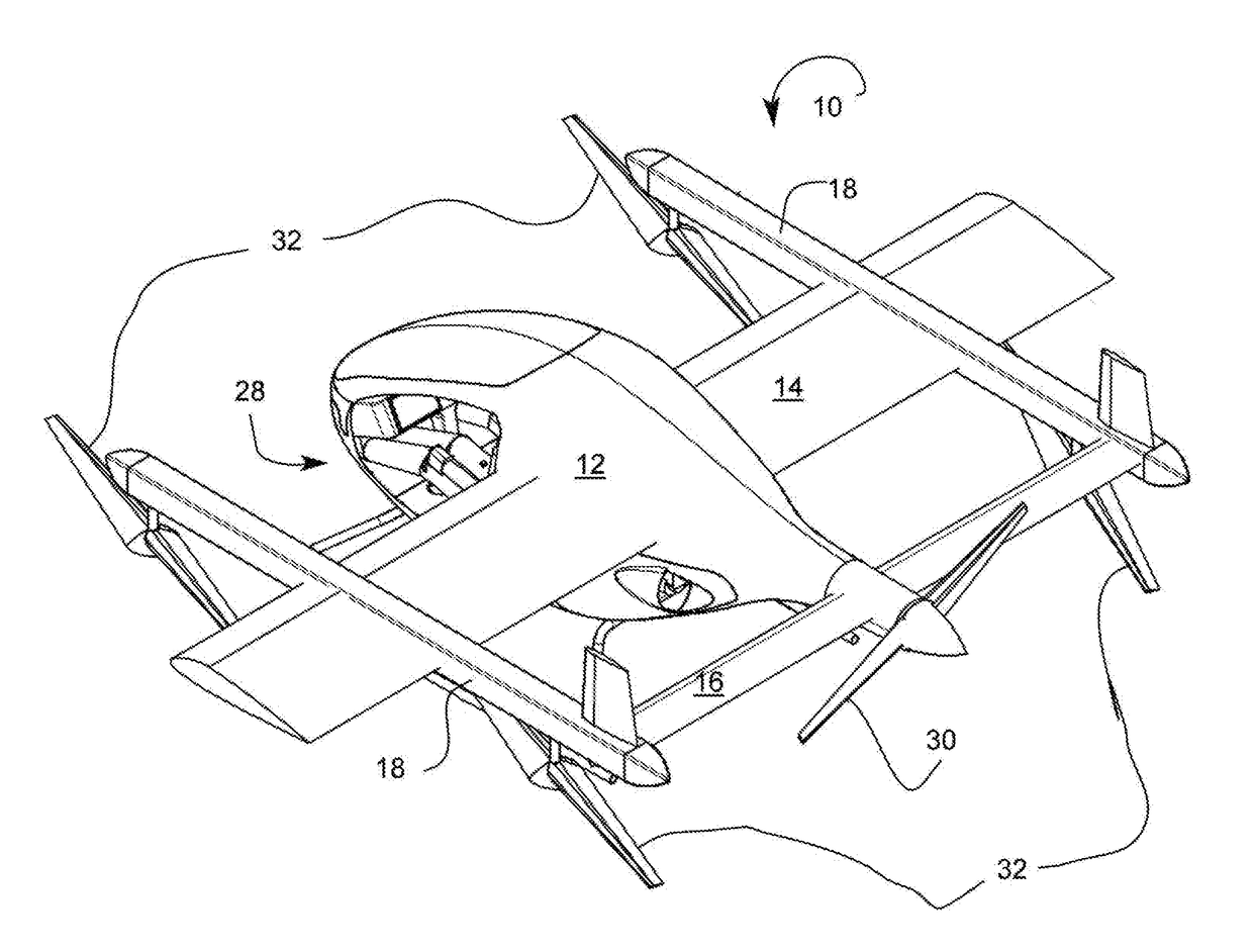
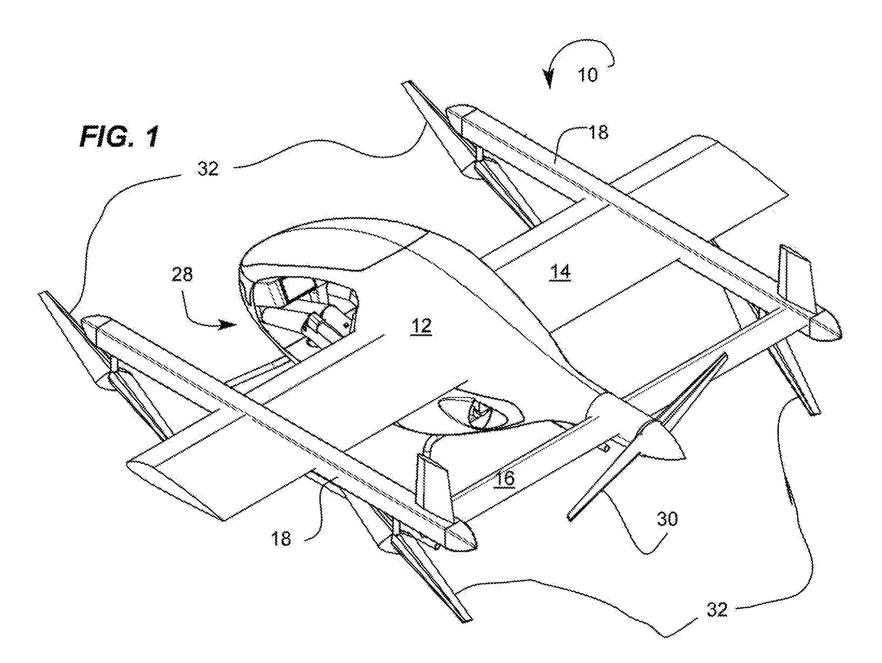
[0011]FIG. 1 is a perspective view of a VTOL high speed aircraft 10 according to an embodiment of the present invention. Referring now FIG. 1, the VTOL high speed aircraft comprises a fuselage, a first pair of wings 14, and a second pair of wings 16. The first pair of wings is the primary wings positioned approximately to the center of the fuselage, and the second pair of wings is the secondary wings forming the tail of the aircraft. The first and second pairs of wings are joined by a pair of booms 18.

[0012]In one embodiment, a drive propeller 30 is provided and at...


PUM


Abstract

A vertical take-off and landing high speed aircraft comprising a fuselage having a first and a second end; a first pair of wings positioned between the first and second end; a secondary pair of wings positioned at the second end, wherein the first and second pairs of wings are joined by a pair of booms, each boom of the pair of booms having an fore end and an aft end; a drive propeller positioned at the first or second end; and a plurality of lift rotors positioned at the fore and aft ends of the pair of booms, the plurality of lift rotors providing a lift force necessary for vertical take-off and landing.

Description

CROSS-REFERENCE TO RELATED APPLICATIONS[0001]N / ABACKGROUND OF THE INVENTION1. Field of the Invention[0002]The present invention generally relates to a vertical take-off and landing flying vehicle, but more particularly to a vertical take-off and landing high speed aircraft.2. Description of Related Art[0003]There has always been a compromise between the ability of a helicopter to take off vertically without a landing strip, and the speed capabilities of an airplane. Helicopters are limited in how fast they can go because of their long rotating blades which move at different relative speeds. Indeed, the forward moving blade has a higher relative speed, while the rearward moving blade has a lower relative speed. As the helicopter moves faster, the forward moving blade approaches the speed of sound and becomes very inefficient, while the backward moving blade encounters what is known as retreating blade stall, meaning that it loses lift. For this reason, helicopters are limited to spee...

Claims


Application Information

Patent Timeline
Patent Type & Authority Applications(United States)
IPC IPC(8): B64C27/14B64C29/00
CPCB64C29/0025B64C27/14B64D35/04
Inventor UPTIGROVE, JOHN
Owner UPTIGROVE JOHN
Why Eureka
Try Eureka