
Method of producing gas separation membrane, gas separation membrane, gas separation membrane module, and gas separator

Inactive Publication Date: 2018-10-18
FUJIFILM CORP
View PDF4 Cites 0 Cited by
  • Summary
  • Abstract
  • Description
  • Claims
  • Application Information

AI Technical Summary

Benefits of technology

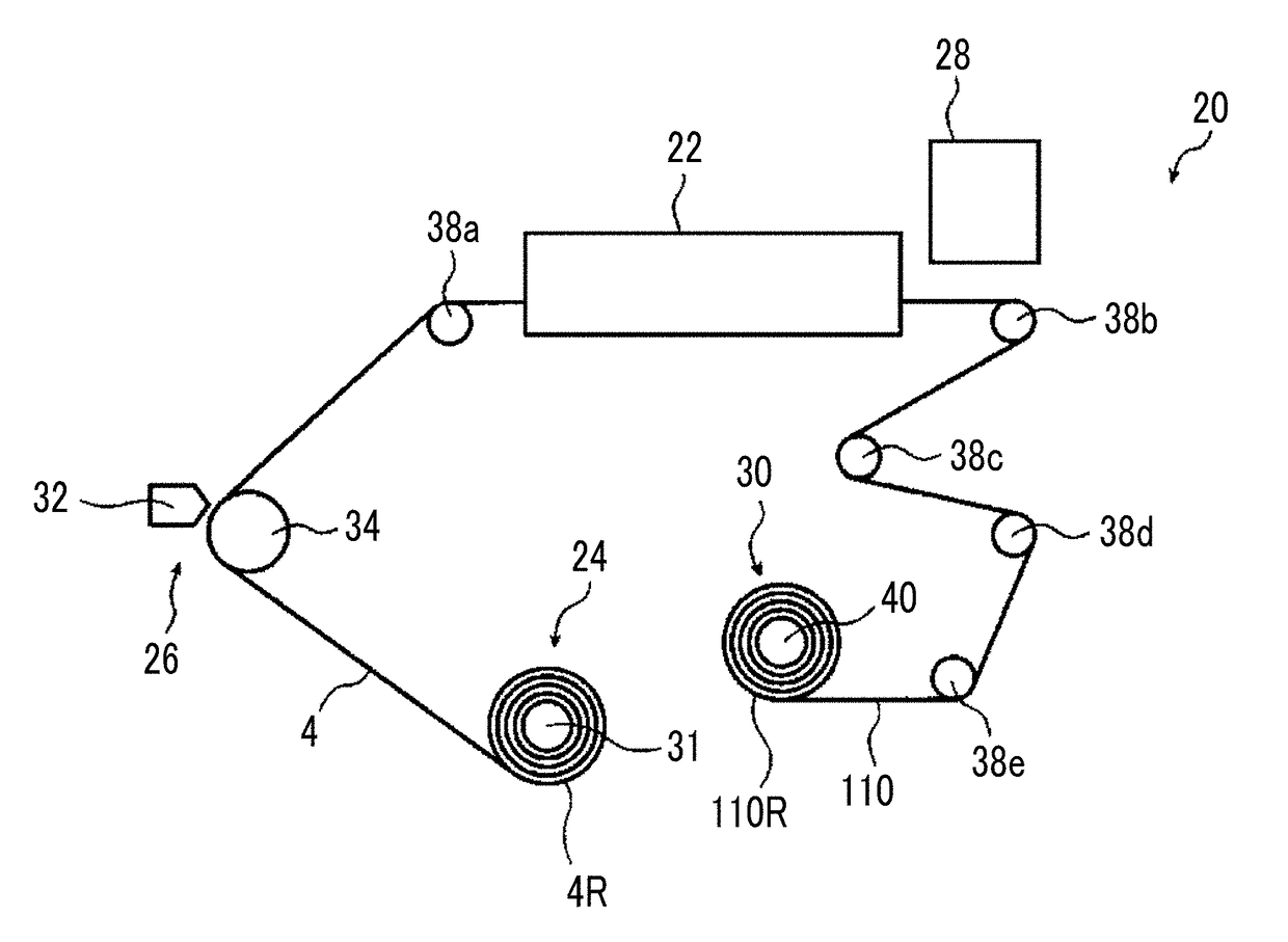
The present invention provides a method for producing a gas separation membrane that has high gas separation selectivity under high pressure and excellent productivity. This is achieved by setting specific ranges for the cumulative irradiation dose at a wavelage of 185 nm and a cumulative irradiation dose at a wavelength of 254 nm in an ultraviolet ozone treatment step of irradiating a resin layer precursor with light containing ultraviolet rays of 185 nm and 254 nm.

Problems solved by technology

Meanwhile, it was understood that the method of using a vacuum plasma treatment or a reduced pressure plasma treatment is basically not suitable for a roll-to-roll system (hereinafter, also referred to as “RtoR”) and further improvement of productivity is required because the cost is extremely high and the running cost is also taken even in a case where facility responses have been made.

Method used


Image

  • Method of producing gas separation membrane, gas separation membrane, gas separation membrane module, and gas separator
  • Method of producing gas separation membrane, gas separation membrane, gas separation membrane module, and gas separator
  • Method of producing gas separation membrane, gas separation membrane, gas separation membrane module, and gas separator

Examples


examples

[0213]The characteristics of the present invention will be described in detail with reference to examples and comparative examples (the comparative examples do not correspond to known techniques) described below. The materials, the amounts to be used, the ratios, the treatment contents, and the treatment procedures shown in the examples described below can be appropriately changed as long as it is within the gist of the present invention. Accordingly, the scope of the present invention should not be limitatively interpreted by the specific examples described below.

[0214]Moreover, “part” and “%” in the sentences are on a mass basis unless otherwise noted.

examples 101 to 106

[0255]—Formation of Module—

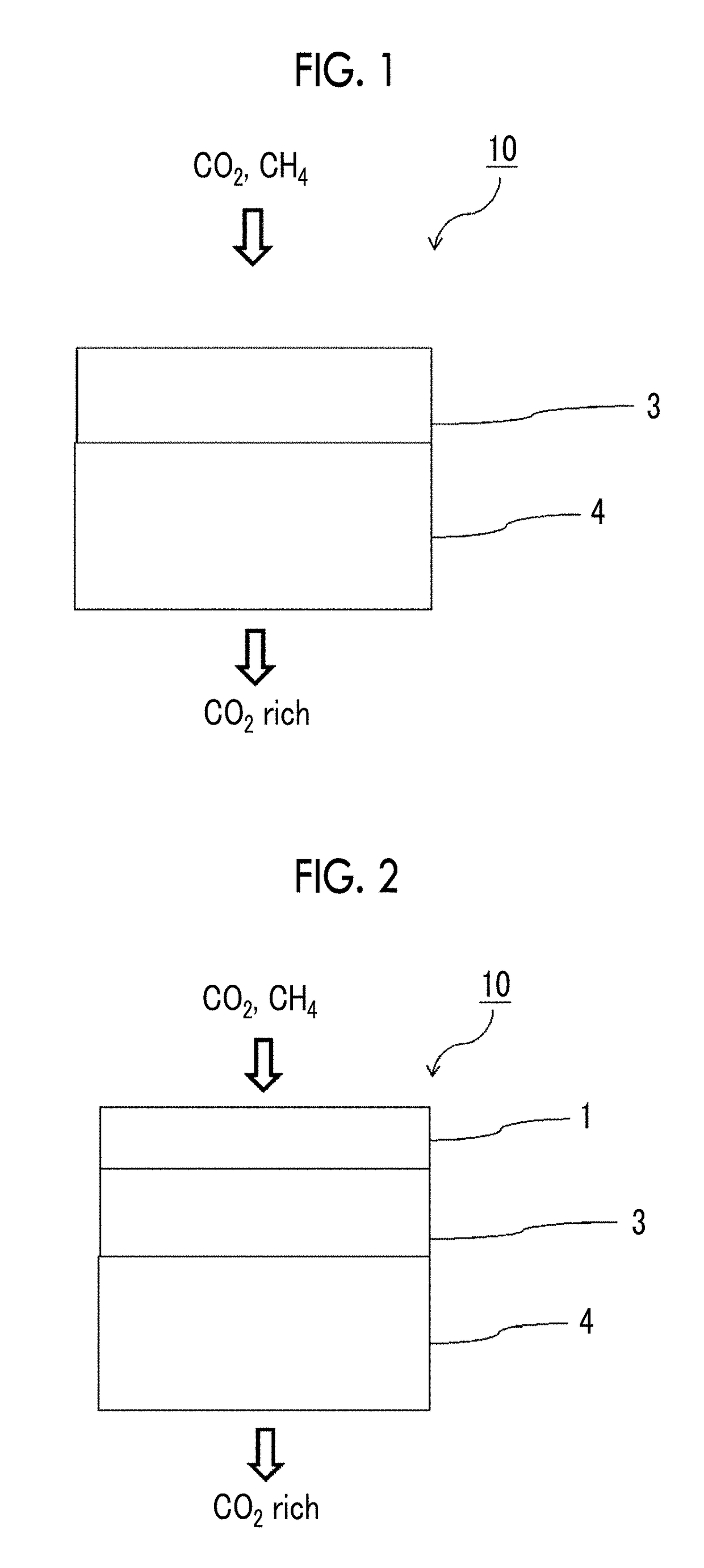
[0256]Spiral type modules were prepared using the gas separation membranes prepared in Examples 1 to 6 with reference to paragraphs to of JP1993-168869A (JP-H05-168869A). The obtained gas separation membrane modules were made into gas separation membrane modules of Examples 101 to 106.

[0257]It was confirmed that the prepared gas separation membrane modules of Examples 101 to 106 were excellent based on the performance of the gas separation membranes incorporated therein.

[0258]In the prepared gas separation membrane modules of Examples 101 to 106, ten portions having a size of 1 cm×1 cm were randomly collected from the center of one surface of a leaf (leaf indicates a portion of a gas separation membrane in which the space on the permeation side in the spiral type module is connected to the central tube and which is folded into an envelope shape with a size of 10 cm×10 cm) and the element ratios of the surface in the depth direction were calculated accord...


PUM

PropertyMeasurementUnit
Thicknessaaaaaaaaaa
Nanoscale particle sizeaaaaaaaaaa

Abstract

A method of producing a gas separation membrane, includes: an ultraviolet ozone treatment of irradiating a resin layer precursor which has a siloxane bond with light containing ultraviolet rays having a wavelength of 185 nm and ultraviolet rays having a wavelength of 254 nm to form a resin layer that contains a compound having a siloxane bond, in which a cumulative irradiation dose of the ultraviolet rays having a wavelength of 185 nm is in a range of 6.0 to 17.0 J / cm2, a cumulative irradiation dose of the ultraviolet rays having a wavelength of 254 nm is in a range of 120 to 330 J / cm2, and the compound having a siloxane bond contained in the resin layer includes a repeating unit represented by Formula (2) or a repeating unit represented by Formula (3).

Description

CROSS-REFERENCE TO RELATED APPLICATIONS[0001]This application is a Continuation of PCT International Application No. PCT / JP2016 / 88806, filed on Dec. 27, 2016, which claims priority under 35 U.S.C. § 119(a) to Japanese Patent Application No. 2016-003797, filed on Jan. 12, 2016. Each of the above application(s) is hereby expressly incorporated by reference, in its entirety, into the present application.BACKGROUND OF THE INVENTION1. Field of the Invention[0002]The present invention relates to a method of producing a gas separation membrane, a gas separation membrane, a gas separation membrane module, and a gas separator. More specifically, the present invention relates to a method of producing a gas separation membrane which has a high gas separation selectivity under a high pressure and an excellent productivity, a gas separation membrane which has a high gas separation selectivity under a high pressure, a gas separation membrane module using the gas separation membrane, and a gas sep...

Claims


Application Information

Patent Timeline
IPC IPC(8): B01D67/00B01D53/22B01D69/12B01D71/70B01D63/10C09D183/04C08J7/04
CPCB01D67/0093B01D53/228B01D69/12B01D71/70B01D63/10C09D183/04C08J7/047B01D2323/345C08J2333/20C08J2483/04B01D53/22B01D2256/245B01D2257/504B01D2258/0233B01D2258/025B01D2258/0283B01D2258/05B01D2323/42C09D183/06C08G77/14Y02C20/40Y02P20/151B01D71/701C08J7/0427B01D63/101B01D67/00933
Inventor YONEYAMA, SATOSHI
Owner FUJIFILM CORP
Learn More