Real time fluid level monitoring system
a fluid level monitoring and real-time technology, applied in liquid/fluent solid measurement, machines/engines, instruments, etc., can solve the problems of introducing human error, slow start up time, dry engine can reach critical damage in as little as six seconds, and cannot give real-time data while the vehicle is moving
- Summary
- Abstract
- Description
- Claims
- Application Information
AI Technical Summary
Benefits of technology
Problems solved by technology
Method used
Image
Examples
first embodiment
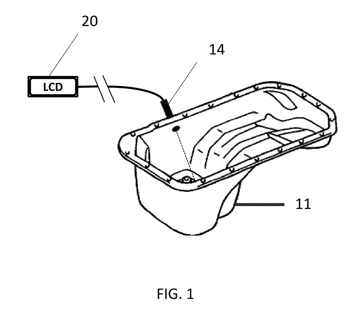
[0029]A more complete representation of the normal operation profile 52 can be viewed in the flow chart of FIG. 4. As shown in the normal operation flow chart, the system 10 is activated when powered on 100, the system 10 then initiates an initial average measurement sequence 102 to determine fluid levels. Next, the system 10 initiates a check for setup file routine 104, if the setup file is not available 106 the system 10 initiates a level calibration routine 108, 208. The level calibration routine 108, 208 can be divided into separate subroutines depending on the need of the users. the level calibration subroutine 108 comprises the steps of setting critical measurement values relating to the oil tank 11. The first step in process involves prompting the user to set tank level values 110 by first setting the “Add” level 112. The Add level is defined as the height of the oil within the tank 11 when the oil volume is at a minimal operational level. In other subroutines with the system...
second embodiment
[0030]the level calibration subroutine 208 shown in FIG. 5 is designed to volumetrically map out a fluid tank 11 to create reusable configurations and profiles of new and existing tanks 11. Similar to the level calibration subroutine 108, the user is prompted to run mapping setup 210 and initiate the fill value 1 subroutine 212. In this routine, the user adds a known quantity of fluid, for example, one gallon. The system 10 next monitors and waits until the fluid is stabilized 214 and saves the height data 216 in connection with user inputted volume data. This subroutine is repeated a number of times for sequential volume and height values and a general volume of the tank 11 is then calculated with the system 10 being able to determine based on the volume and height level data where the Critically Low level, Add level, and Full level are. The data is then stored 218 in a new mapped setup file and the subroutine 208 returns to the normal operation routine 52.
[0031]Upon completion of ...
PUM
 Abstract
Description
Claims
Application Information
 - R&D
- Intellectual Property
- Life Sciences
- Materials
- Tech Scout
- Unparalleled Data Quality
- Higher Quality Content
- 60% Fewer Hallucinations
Browse by: Latest US Patents, China's latest patents, Technical Efficacy Thesaurus, Application Domain, Technology Topic, Popular Technical Reports.
© 2025 PatSnap. All rights reserved.Legal|Privacy policy|Modern Slavery Act Transparency Statement|Sitemap|About US| Contact US: help@patsnap.com


