Heliostat characterization using starlight

a technology of starlight and heliostats, applied in instruments, solar heat systems, lighting and heating apparatus, etc., can solve the problems of largely dropping out errors due to refraction, and achieve the effect of slow construction of slope errors and canting maps

Inactive Publication Date: 2018-10-18
SOLARRESERVE TECH
View PDF2 Cites 9 Cited by
  • Summary
  • Abstract
  • Description
  • Claims
  • Application Information

AI Technical Summary

Benefits of technology

[0071]One way to deal with this would be to move the camera around. As the camera moves, different parts of the firmament would be reflected onto different camera pixels, allowing slope error and canting maps to be slowly constructed.
[0072]A better approach, however, is to move the firmament relative to the camera(s). There are two ways to move the firmament. One is simply to wait. Due to earth rotation, the firmament predictably moves naturally. Over a long enough period of time, stars or planets will sweep across most regions of the heliostat's facets, and a map of the facet can be constructed. The other way to move the firmament is to make it appear to move, by controllably articulating the heliostat to a predetermined orientation, or a

Problems solved by technology

But the effect is small unless the stars and/or planets are near the horizon, and further, since canting and slope error measurements are really the measurement of relative differences in a

Method used


Image

  • Heliostat characterization using starlight
  • Heliostat characterization using starlight
  • Heliostat characterization using starlight

Examples


Embodiment Construction

[0099]Embodiments described herein are exemplary and do not represent all possible embodiments of the principles taught by the present invention. In particular, embodiments of the present invention have direct application in the field of concentrating solar power, particularly concentrating solar power including the use of heliostats to redirect sunlight onto a fixed focus in which concentrated sunlight may be converted into other forms of energy such as heat or electrical energy. Nevertheless, the apparatus and methods described herein can be applied and adapted by those skilled in the art for use in alternative applications in which the optical characteristics of a mirror must be measured from a distance.

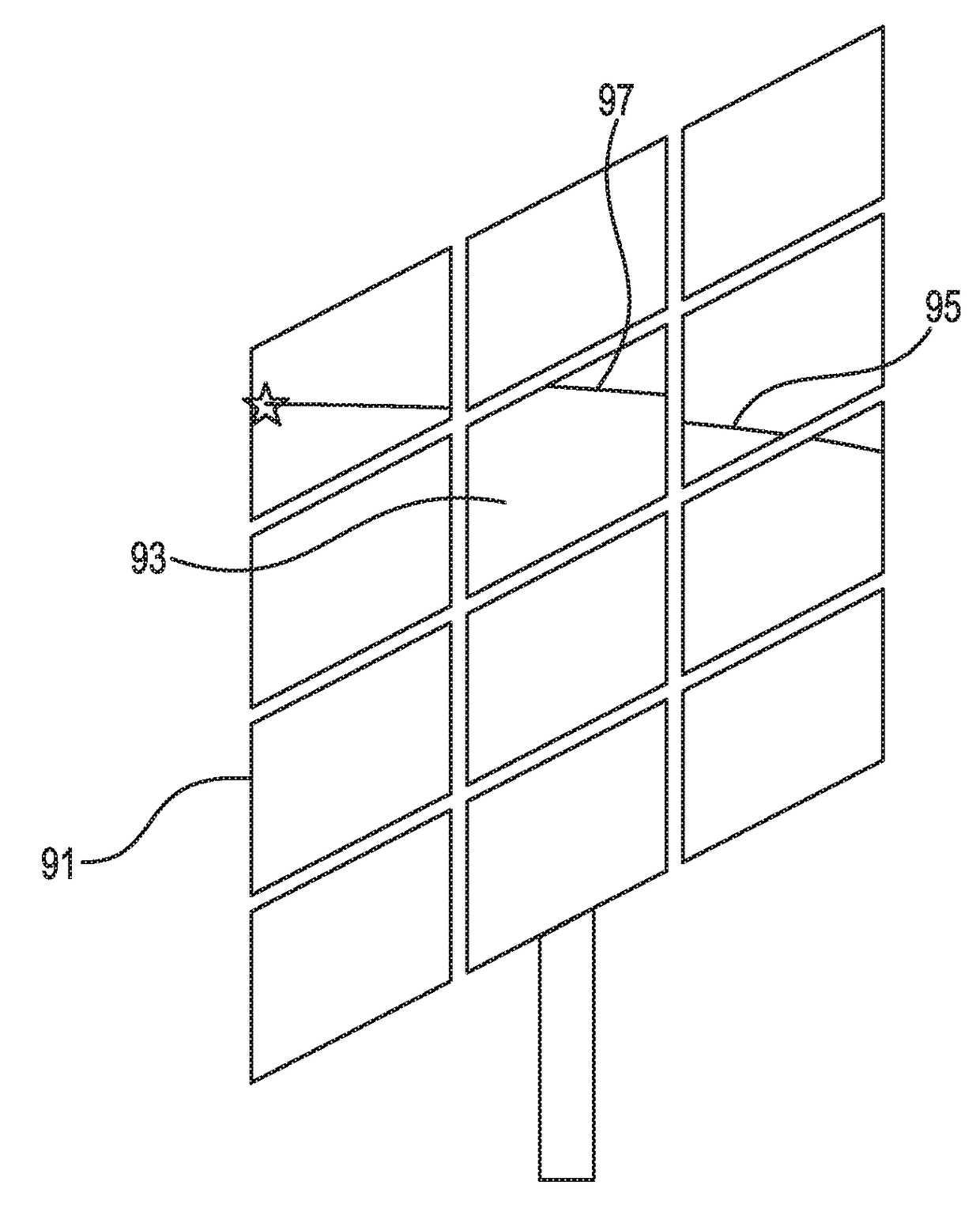
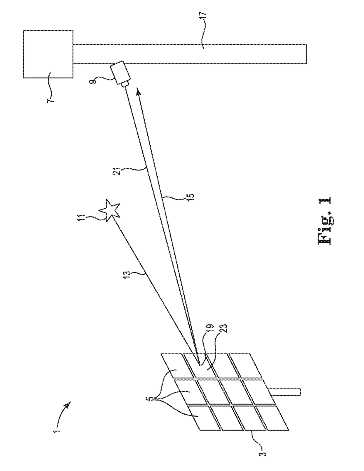
[0100]As shown, in FIG. 1, an exemplary CSP system 1 can include an array of heliostats 3 that redirect and concentrate sunlight onto a focus area 7 of a tower 17. Each heliostat 3 may include one or more mirror facets 5.

[0101]An embodiment of the invention includes a digital imag...


PUM


Abstract

The present invention offers an improvement to existing canting, slope error, and/or pointing measurement approaches, by using one or more cameras to observe the reflections of points of light in the firmament, such as the reflections of stars and/or planets as visible within the night sky in the heliostat facets. An illustrative heliostat measurement system comprises a plurality of heliostats, and at least one camera that observes at least one heliostat. The heliostats reflect an image of the firmament that can be observed by the at least one camera. The system further comprises (i) at least one captured image of the firmament reflected from at least one of the heliostats; and (ii) a computer comprising programming that determines a heliostat imperfection from the captured image, wherein the heliostat imperfection is selected from at least one of a slope error, a canting error, and a pointing error.

Description

PRIORITY[0001]This application claims the benefit of U.S. Provisional Patent Application Ser. No. 62 / 182,196, filed on Jun. 19, 2015, the entire disclosure of which is incorporated herein by reference for all purposes.FIELD OF THE INVENTION[0002]The present invention relates to the optical alignment of heliostats used to reflect sunlight to a target in a solar power plant in the field of concentrating solar power (CSP). More specifically, the invention relates to the relative alignment of individual facets of a multi-facet heliostat or a single-facet heliostat, measurement of the shape of individual facets, and an overall pointing of one or more heliostats.BACKGROUND OF THE INVENTION[0003]The use of heliostats in the field of concentrating solar power (CSP) is well established in the prior art. A typical CSP system includes at least one centralized tower and a plurality of heliostats corresponding to each centralized tower. The tower is centralized in the sense that the tower serves...

Claims


Application Information

Patent Timeline
IPC IPC(8): G01B11/26F24S23/70F24S50/20
CPCG01B11/26F24S23/70Y02E10/47F24S50/20F24S2050/25
Inventor HINES, BRADEN E.
Owner SOLARRESERVE TECH
Why Eureka
Try Eureka