
Defect inspection apparatus, method, and program

Active Publication Date: 2018-10-18
FUJIFILM CORP
View PDF0 Cites 2 Cited by
  • Summary
  • Abstract
  • Description
  • Claims
  • Application Information

AI Technical Summary

Benefits of technology

The invention is a defect inspection system that uses images of industrial products to detect any defects that might occur. The system allows an image interpreter to effectively and accurately identify defects, which can then be displayed on a screen. The system also predicts the growth and spread of possible defects over time, which improves background knowledge and precision. The system can also continuously or gradually change the feature range of a possible defect, resulting in increased efficiency and accuracy of defect detection.

Problems solved by technology

In a case where an accident has once occurred in a facility, such as a pipeline, used to, for example, carry oils, the accident causes serious damage to society.
It is difficult to remove a facility, such as a pipeline, for inspection, and therefore, a facility, such as a pipeline, is usually inspected by using a nondestructive inspection that involves irradiation of an inspection target, such as a pipeline, with light rays or radiation rays.
In an inspection, various types of defects are detected, such as stains, cracks, dust, and chipping, which vary in form and size, and furthermore, a considerable number of defects are detected.
Therefore, it takes a considerable time to exhaustively check these defects.
Accordingly, it is required to increase precision and efficiency in interpretation of an image and checking of defects; however, JP-2011-252846A or JP2010-272528A does not disclose a technique for increasing efficiency in interpretation of an image of an inspection target.

Method used


Image

  • Defect inspection apparatus, method, and program
  • Defect inspection apparatus, method, and program
  • Defect inspection apparatus, method, and program

Examples


Embodiment Construction

[0045]Hereinafter, a defect inspection apparatus, method, and non-transitory computer readable recording medium storing a program according to an embodiment of the present invention will be described with reference to the attached drawings.

Configuration of Defect Inspection Apparatus

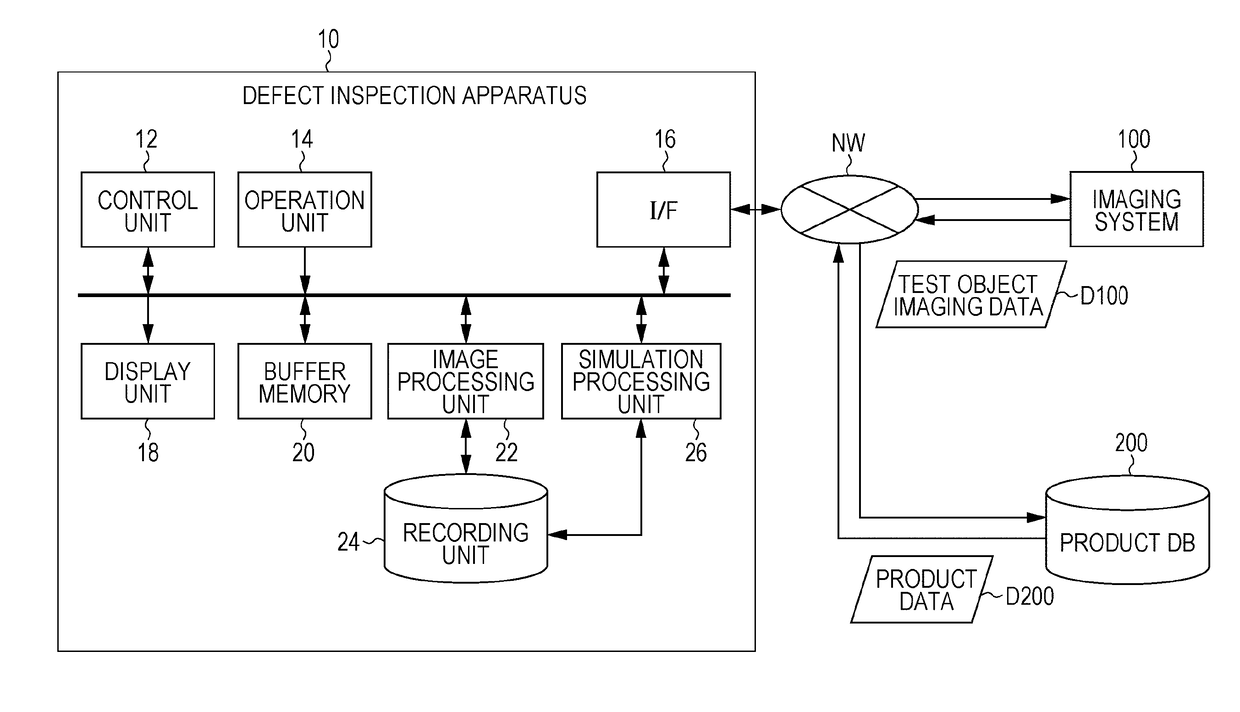
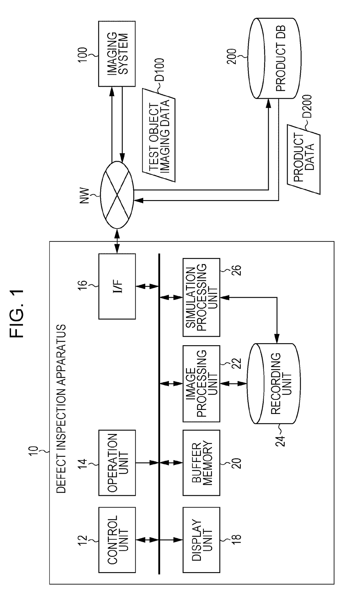
[0046]FIG. 1 is a block diagram illustrating a defect inspection apparatus according to an embodiment of the present invention.

[0047]A defect inspection apparatus 10 according to this embodiment is an apparatus that detects possible defects from a captured image of an inspection-target industrial product (test object) and displays the possible defects, and is an apparatus for assisting an image interpreter in diagnosing a defect in the test object. As illustrated in FIG. 1, the defect inspection apparatus 10 according to this embodiment includes a control unit 12, an operation unit 14, an input / output interface (hereinafter referred to as an I / F (interface)) 16, a display unit 18, a buffer memory 20, an ...


PUM


Abstract

There are provided a defect inspection apparatus, method, and program for, in a case of using an image of an inspection-target industrial product (test object) to conduct an inspection to check whether defects are present, allowing an image interpreter to precisely and efficiently detect defects. A possible-defect image D3 indicating a crack-like defect and a simulation result image P3 indicating the predicted growth of the crack-like defect are displayed. Sliders L1 and L2 and checkboxes CB1 are used to enable selection of possible defects and simulation results to be displayed. An image interpreter can use the checkboxes CB1 to select a type of possible defect to be displayed, and can use the sliders L1 and L2 to select possible defects to be displayed on the basis of the wall thickness of portions in which possible defects are detected and the size of possible defects.

Description

CROSS REFERENCE TO RELATED APPLICATIONS[0001]This application is a Continuation of PCT International Application No. PCT / JP2016 / 084902 filed on Nov. 25, 2016, which claims priority under 35 U.S.C § 119(a) to Patent Application No. 2016-015667 filed in Japan on Jan. 29, 2016, all of which are hereby expressly incorporated by reference into the present application.BACKGROUND OF THE INVENTION1. Field of the Invention[0002]The present invention relates to a defect inspection apparatus, method, and program and specifically relates to a defect inspection apparatus, method, and program for providing assistance in inspecting defects using an image of an inspection-target industrial product.2. Description of the Related Art[0003]JP-2011-252846A discloses a remaining-life diagnostic apparatus for diagnosing the remaining life of an inspection target relating to a power facility.[0004]JP2010-272528A discloses an inspection apparatus and method for inspecting the surface of a sample. JP2010-272...

Claims


Application Information

Patent Timeline
IPC IPC(8): G01N21/88G01N23/18G01N23/203G06F17/50
CPCG01N21/8851G01N23/18G01N23/203G06F17/5009G01N2021/8887G05B19/41875G05B19/042G05B2219/45233G06F30/20Y02P90/02
Inventor KANEKO, YASUHIKO
Owner FUJIFILM CORP
Features
  • Generate Ideas
  • Intellectual Property
  • Life Sciences
  • Materials
  • Tech Scout
  • Unparalleled Data Quality
  • Higher Quality Content
  • 60% Fewer Hallucinations
Learn More