

Damping skin system for protecting composite parts
- Summary
- Abstract
- Description
- Claims
- Application Information
AI Technical Summary
Benefits of technology
Problems solved by technology
Method used
Image

Examples
Embodiment Construction
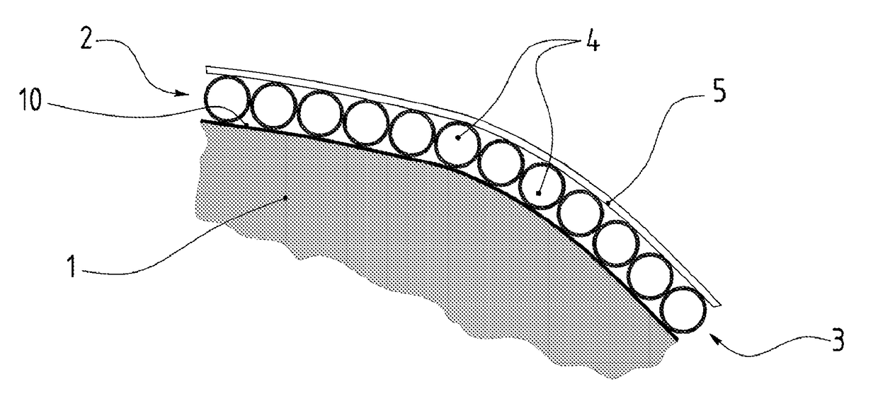
[0056]FIG. 1 shows an object 1, a part made of a composite material for example, whose external wall 10 is covered with a damping skin 2 according to the invention.
[0057]Said damping skin 2 consists of two layers, a first layer 3 consisting of the juxtaposition of hollow spheres 4, fixed to the wall 10, and a second layer 5, covering the first, and made of a material having plastic deformation properties.
[0058]The hollow spheres are of a known type, already used in the field of shock absorbers for example, they can be made of different materials, including metal or synthetic materials as well.
[0059]The layer 5 consists of a sheet which can be made in different manners, of a composite tissue, or of several composite tissues stratified between them, the number of tissues, as well as their thickness and their texture being chosen according to the use of the skin.
[0060]Said tissues are preferably, but not restrictively, made of aramid polymer.
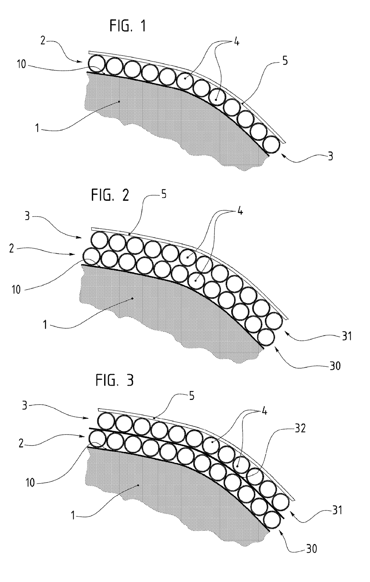
[0061]FIG. 2 shows that, according to a vari...
PUM
| Property | Measurement | Unit |
|---|---|---|
| Thickness | aaaaa | aaaaa |
| Electrical conductivity | aaaaa | aaaaa |
| Diameter | aaaaa | aaaaa |
Abstract
Description
Claims
Application Information