

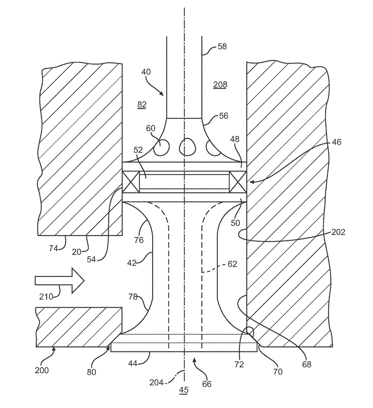
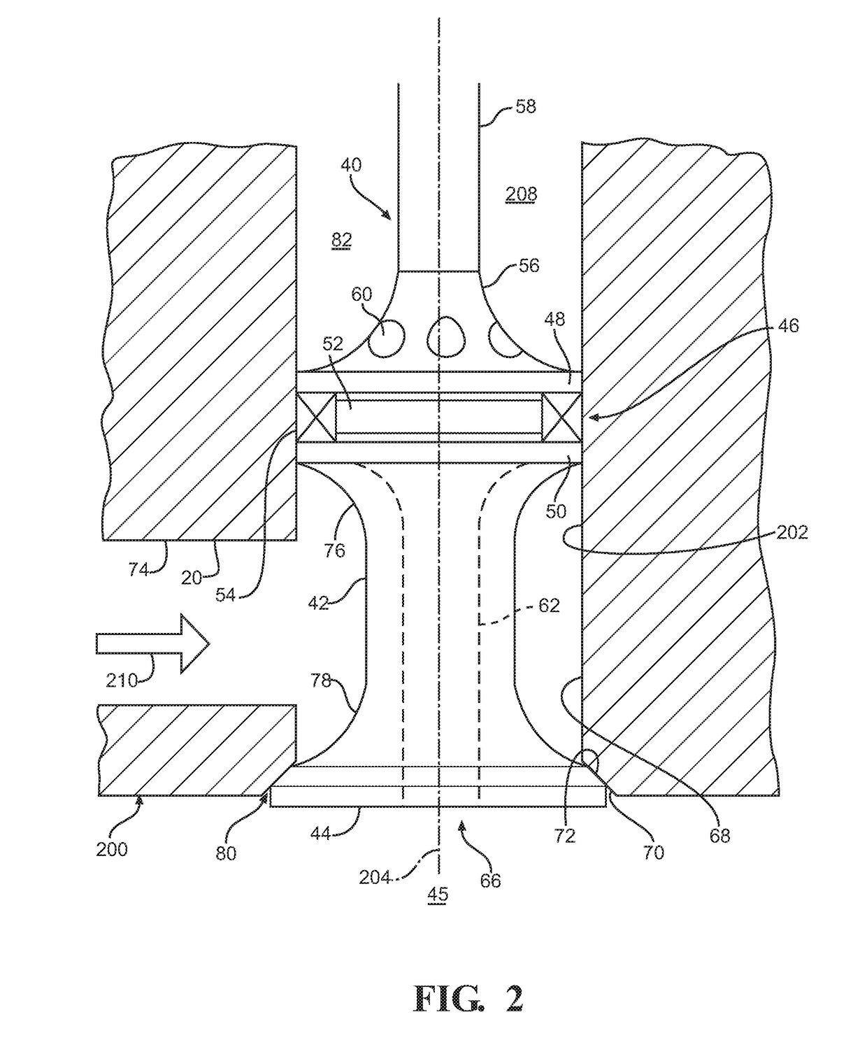
Reciprocating expander valve
a technology of expander valve and valve seat, which is applied in the direction of steam engine plants, mechanical equipment, machines/engines, etc., can solve the problems of difficult to have both valve seats perfectly sealed, and achieve the effects of reducing the net gas-generated forces acting on the valve, reducing the return spring force, and facilitating operation
- Summary
- Abstract
- Description
- Claims
- Application Information
AI Technical Summary
Benefits of technology
Problems solved by technology
Method used
Image

Examples
Embodiment Construction
[0026]Those having ordinary skill in the art will recognize that terms such as “above,”“below,”“upward,”“downward,”“top,”“bottom,” etc., are used descriptively for the figures, and do not represent limitations on the scope of the disclosure, as defined by the appended claims. Furthermore, the teachings may be described herein in terms of functional and / or logical block components and / or various processing steps. It should be realized that such block components may be comprised of any number of hardware, software, and / or firmware components configured to perform the specified functions.
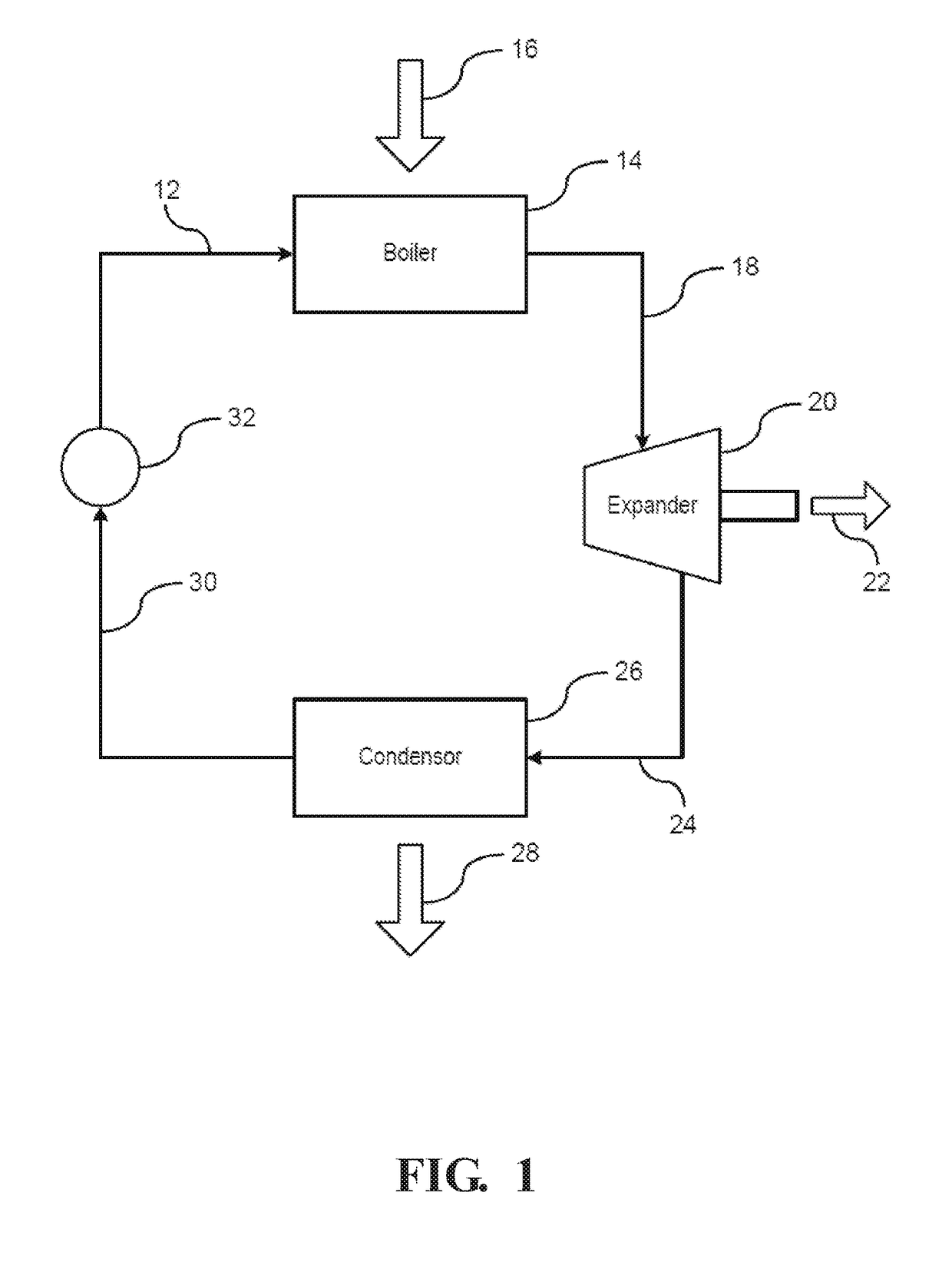
[0027]Referring to the FIGS., wherein like numerals indicate like parts throughout the several views, a heat recovery system is generally shown at 10 in FIG. 1. Referring to FIG. 1, heat recovery systems utilize energy that would typically be exhausted into the environment and wasted. A Rankine cycle heat recovery system utilizes heat from a heat exhaust system to convert the exhaust heat into input en...
PUM
 Abstract
Description
Claims
Application Information