System for continuously calibrating a magnetic imaging array

a magnetic imaging array and continuous calibration technology, applied in the field of magnetic imaging array calibration, can solve problems such as additional complications

Inactive Publication Date: 2018-11-01
QUSPIN
View PDF8 Cites 36 Cited by
  • Summary
  • Abstract
  • Description
  • Claims
  • Application Information

AI Technical Summary

Benefits of technology

[0006]Optically-pumped magnetometers can be arranged into flexible arrays, which results in the need to determine all sensor positions and orientations every time the array configuration is changed. In addition, the orientation of the sensing axes of each magnetometer in the array is affected by cross-talk from neighboring sensors. Furthermore, parameters such as the gain, the bandwidth,

Problems solved by technology

For some OPMs, an additional complication comes from the fact that the position at which the magnetic field i

Method used


Image

  • System for continuously calibrating a magnetic imaging array
  • System for continuously calibrating a magnetic imaging array
  • System for continuously calibrating a magnetic imaging array

Examples


example 1

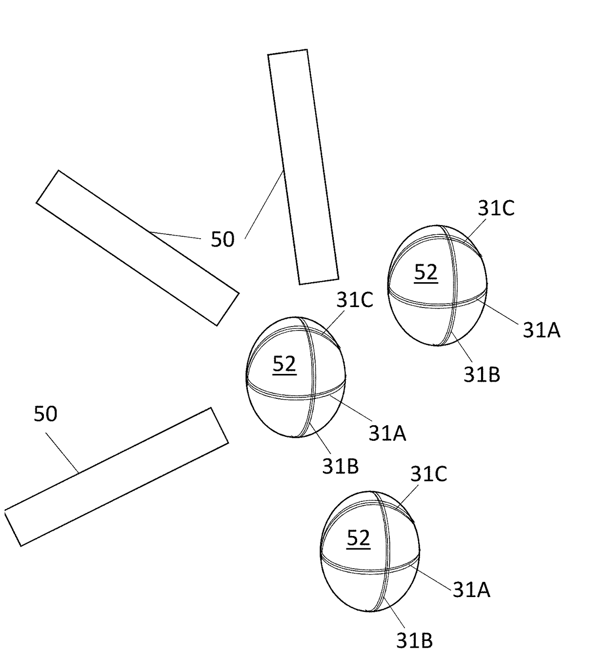
[0027]As an example, a simple magnetic imaging array has been constructed out of three optically-pumped magnetometers (OPMs) 50 as shown in FIG. 5. Each OPM 50 measured magnetic field(s) in two nearly orthogonal directions giving two channels of output data each. A schematic diagram of the imaging array is shown in FIG. 5. Three coils 31A, 31B, and 31C, were wrapped around each of three spheres 52 in nearly orthogonal directions serving as three dipolar sources. The spheres 52 were arranged and their relative positions and orientations measured carefully. The magnetic field of each of the dipolar sources was calculated relative to the sources themselves. Oscillating non-target magnetic fields were applied to the nine dipoles 31A, 31B, and 31C at modulation frequencies of 77 Hz, 78 Hz, 79 Hz, 80 Hz, 81 Hz, 82 Hz, 83 Hz, 84 Hz, and 85 Hz, respectively. The fields were recorded continuously in each of the six channels of the three OPMs 50. In order to record data with the OPM array sim...

example 2

[0028]The above example described how the present invention was used to continuously calibrate the positions, orientations and the overall gain of the imaging array. In the current example the bandwidth and related frequency dependence of the gain were continuously calibrated. Since in most OPMs, the bandwidth depends on laser parameters as well as DC background fields, it is prone to drift and requires frequent recalibration. In this example, a current dipole was continuously driven with the sum of several sinusoidal modulations at 100 Hz, 200 Hz, 300 Hz and 400 Hz of the same amplitude. The magnetic field was recorded continuously. With a bandwidth of the OPM around 150 Hz, the peaks in the power spectrum corresponding to these modulation fields were clearly seen to decrease with higher frequency. Notch filters were applied around the modulation peaks to the time series in order to minimize the effect of the modulation on the data. The amplitudes of the modulation fields at the di...


PUM


Abstract

A calibration system and method is described to continuously measure and adjust several parameters of a magnetic imaging array. One or more non-target magnetic field source(s) are used to generate a well-defined and distinguishable spatial magnetic field distribution. The magnetic imaging array is used to measure the strength of the non-target magnetic fields and the information is used to calibrate several parameters of the array, such as, but not limited to, effective magnetometer positions and orientations, gains and their frequency dependence, bandwidth, and linearity. The calibration can happen continuously or periodically, while the imaging array is operating to create magnetic field images, if the modulation frequencies for calibration are outside the frequency window of interest.

Description

[0001]The following application is an application for patent under 35 USC 111 (a). This invention was made with government support under HD074495 awarded by the National Institutes of Health. The government has certain rights in the invention.FIELD OF INVENTION[0002]This disclosure relates to the field of calibrating a magnetic imaging array, specifics y a system and method thereof.BACKGROUND[0003]Optically pumped magnetometers (OPMs), also called atomic magnetometers, optical magnetometers, or optical atomic magnetometers, are used in a number of scientific and advanced technology applications including medical imaging. In their simplest form, these sensors contain a light source, a container to hold atoms, and a detector. The light source may be a laser or other optical device used to produce light of a certain wavelength. The container may be a vapor cell or other device used to house atoms. The detector would necessarily be specific to the light output.[0004]Single OPMs or small...

Claims


Application Information

Patent Timeline
IPC IPC(8): G01R33/00G01R33/032
CPCG01R33/032G01R33/0035
Inventor KNAPPE, SVENJAALEM, ORANGSHAH, VISHAL
Owner QUSPIN
Why Eureka
Try Eureka