
LED lamp sources, and the manufacturing methods and the backlight modules thereof

Active Publication Date: 2018-11-01
TCL CHINA STAR OPTOELECTRONICS TECH CO LTD
View PDF8 Cites 4 Cited by
  • Summary
  • Abstract
  • Description
  • Claims
  • Application Information

AI Technical Summary

Benefits of technology

The present patent is about improving the optical color uniformity of LED lamps and increasing the number of LEDs per unit area (In-Bin rate) while reducing the cost of the backlight module. This is achieved by using a white reflective layer that reflects light emitted from the four sides of the LED lamp source, resulting in a more uniform optical color. Additionally, the number of LEDs may be reduced, which decreases the cost of the backlight.

Problems solved by technology

However, the uniformity of the optical colors of the four side emission LED is not good enough, that is, the In-Bin rate, i.e., light adoption rate of the LED is low, and this leads to high cost of backlight modules of the LED lamp source.

Method used


Image

  • LED lamp sources, and the manufacturing methods and the backlight modules thereof
  • LED lamp sources, and the manufacturing methods and the backlight modules thereof
  • LED lamp sources, and the manufacturing methods and the backlight modules thereof

Examples


Embodiment Construction

[0015]Embodiments of the invention will now be described more fully hereinafter with reference to the accompanying drawings, in which embodiments of the invention are shown.

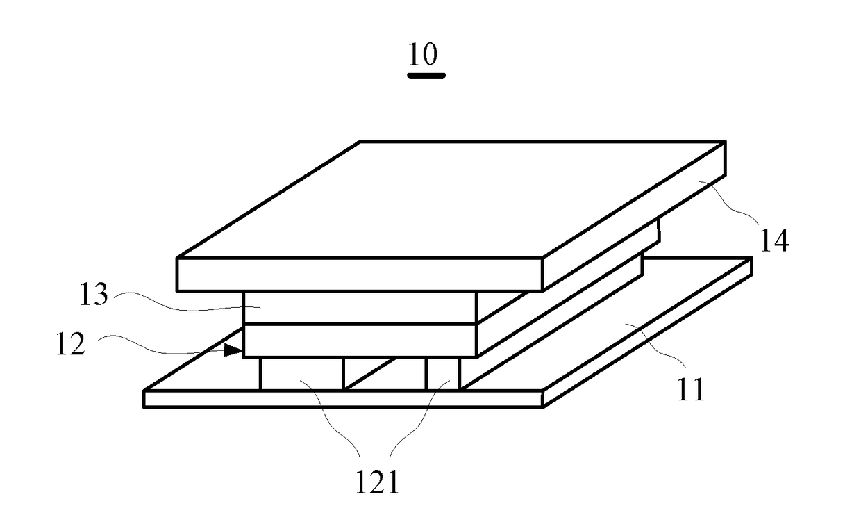
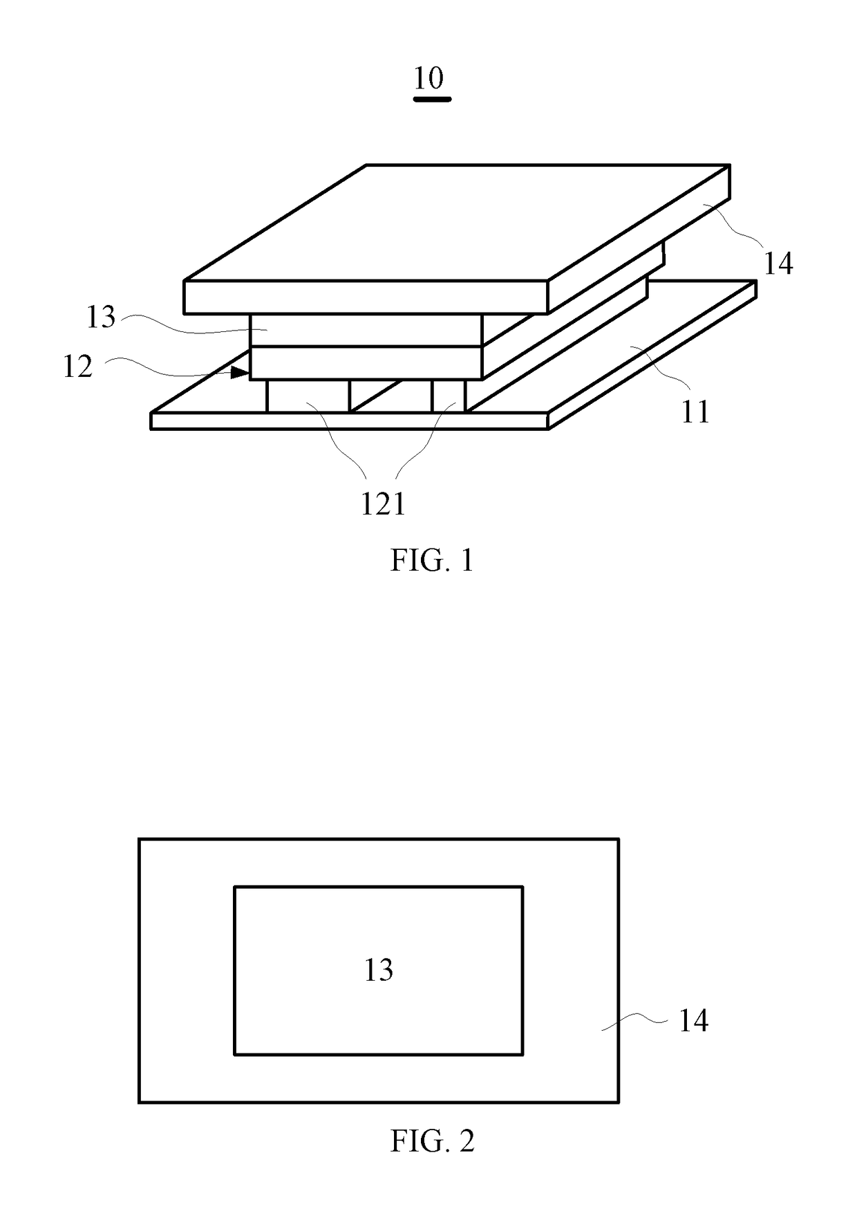
[0016]FIG. 1 is a schematic view of the LED lamp source in accordance with one embodiment of the present disclosure. The LED lamp source 10 includes a substrate 11 and a LED chip 12, fluorescent adhesive 13, and a white reflective layer 14 fixed on the substrate 11. The substrate 11 may be sapphire. The LED chip 12 is a flip chip configured with a metallic electrode 121, and the LED chip 12 emits blue light when the metallic electrode 121 is electrified. The fluorescent adhesive 13 encapsulates the LED chip 12 on the substrate 11 such that the fluorescent adhesive 13 is a rectangular structure as a whole. As such, the encapsulated LED lamp source 10 is a rectangular structure. The fluorescent adhesive 13 is encapsulation adhesive doped with uniformly distributed fluorescent powder. The yellow light emitted by the...


PUM


Abstract

The present disclosure relates to a LED lamp source and the manufacturing method and the backlight module thereof. The LED lamp source includes a substrate and a LED chip, fluorescent adhesive, and a white reflective layer being fixed on the substrate. The fluorescent adhesive encapsulates the LED chip on the substrate, and the white reflective layer is configured for reflecting light beams emitted from the fluorescent adhesive and being radiated on the white reflective layer. A positive projection of the fluorescent adhesive on the substrate is within the positive projection of the white reflective layer on the substrate.

Description

BACKGROUND OF THE INVENTION1. Field of the Invention[0001]The present disclosure relates to display technology, and more particularly to a light emitting diode (LED) and the manufacturing method and the backlight module thereof.2. Discussion of the Related Art[0002]Four side emission LED is a lamp source, which is formed by coating a fluorescent adhesive (phosphor colloid layer) and a white reflective layer on a flip chip. The LED lamp source forms a rectangular light-emitting surface on a diffusion plate, which is characterized by advantages, such as small dimension and high driving power, but also the good local dimming performance may be realized. As such, the high-dynamic range (HDR) may be realized. However, the uniformity of the optical colors of the four side emission LED is not good enough, that is, the In-Bin rate, i.e., light adoption rate of the LED is low, and this leads to high cost of backlight modules of the LED lamp source.SUMMARY[0003]The present disclosure relates ...

Claims


Application Information

Patent Timeline
IPC IPC(8): H01L33/50H01L33/60F21V8/00
CPCH01L33/507H01L33/60G02B6/0073H01L33/54H01L2933/0041H01L2933/005H01L2933/0058G02F1/133603H01L33/52H01L33/0095H01L33/483
Inventor FAN, YONGHSIAO, YU-CHUNCHANG CHIEN, SHENG-JER
Owner TCL CHINA STAR OPTOELECTRONICS TECH CO LTD
Learn More