Valve sealing tissue and mesh structure

a valve and mesh technology, applied in the field of valve sealing tissue and mesh structure, can solve the problems of paravalvular leakage and rise of prosthetic valves, and achieve the effect of reducing paravalvular leakage and reducing leakag

Pending Publication Date: 2018-11-15
EDWARDS LIFESCIENCES CORP
View PDF2 Cites 7 Cited by
  • Summary
  • Abstract
  • Description
  • Claims
  • Application Information

AI Technical Summary

Benefits of technology

[0003]One aspect of the invention provides a prosthetic valve design, such as a cardiac valve design, that reduces paravalvular leakage. Leakage is reduce by associating a tissue liner with a mesh support structure. The tissue liner may be preferred over other liners as tissue is impermeable to fluid flow.
[0013]One aspect of the invention provides a method of preventing paravalvular leakage through a prosthetic valve. The method generally includes the steps of providing a prosthetic valve with a support structure having an outer layer and lining an inside surface of the outer layer with a tissue liner.

Problems solved by technology

One complication that can arise with prosthetic valves is paravalvular leakage, which is blood flowing around the valve, rather than through the valve.
This can result when the valve is not properly seated in the native valve annulus, or when there is a pathway for blood to flow between the leaflets of the prosthetic valve and the anchoring structure used to support the prosthetic valve leaflets.
The latter form of leakage, however, is typically a result of a design flaw or defective valve mechanism.

Method used


Image

  • Valve sealing tissue and mesh structure
  • Valve sealing tissue and mesh structure
  • Valve sealing tissue and mesh structure

Examples


first embodiment

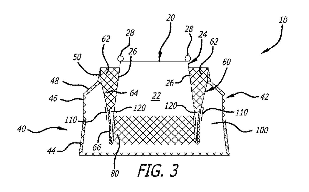
[0035]Paravalvular leakage is prevented, in part, by strategic placement of material on the various section of the support structure 40. In a first embodiment, shown in FIG. 3, includes three protective liners. An outer liner 100 is sewn into the inside surface of the outer layer 42. Specifically, the outer liner 100 spans the flared section 44 and may extend up into the upright section 46 and tapered section 48. All of the liners described herein are preferably circumferential. Non-limiting examples of tissue liner materials include: bio-expandable materials, impermeable fabric, compliant polymers, molded polymers, and hydrogels. It has been found that an impermeable tissue liner performs superiorly in comparison to a woven polyester liner by preventing blood flow through the outer layer 42 of the support structure 40. Furthermore, in all embodiments, fabric may be adhered to the tissue liners to encourage further ingrowth of native tissue.

[0036]The outer tissue liner 100 is attach...

second embodiment

[0041]In a second embodiment, shown in FIG. 4, the extra material of the valve leaflets 22, forming the inner liner 120, is routed to an inside surface of the inner layer 80, and wraps around the third folded section 66 of the middle layer 60.

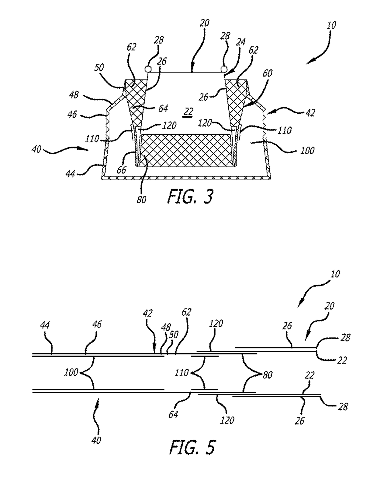
[0042]Each of the embodiments of the device 10 described herein has a delivery configuration and a deployed configuration. In the delivery configuration, the folds are straightened and the mesh support structure is in the form of an elongated tube. The liners are attached to the support structure such that, upon folding, the liners are appropriately placed.

[0043]The delivery configuration of the embodiment of FIG. 3 is shown in FIG. 5. FIG. 5 shows that in the delivery configuration, support structure 40 is a continuous tube that includes layers 42, 60 and 80. When extended the order, moving from left to right as shown, of the various sections and layers becomes outer layer 42, with sections 44, 46, 48 and 50. Liner 100 is contained within the ...


PUM


Abstract

A prosthetic valve device that includes multiple layers and liners attached to various locations on the layers to prevent paravalvular leakage.

Description

RELATED APPLICATIONS[0001]This application claims priority to U.S. Provisional Application Ser. No. 62 / 506,480 filed May 15, 2017 entitled Valve Sealing Tissue And Mesh Structure, which is hereby incorporated herein by reference in its entirety.BACKGROUND OF THE INVENTION[0002]Transcatheter valve repair devices and valves are useful in repairing or replacing defective cardiac valves, typically using a catheter delivery system. One complication that can arise with prosthetic valves is paravalvular leakage, which is blood flowing around the valve, rather than through the valve. This can result when the valve is not properly seated in the native valve annulus, or when there is a pathway for blood to flow between the leaflets of the prosthetic valve and the anchoring structure used to support the prosthetic valve leaflets. The former cause is mitigated through proper valve placement and sizing. The latter form of leakage, however, is typically a result of a design flaw or defective valv...

Claims


Application Information

Patent Timeline
Patent Type & Authority Applications(United States)
IPC IPC(8): A61F2/24
CPCA61F2/2418A61F2/2409A61F2/2427A61F2250/0063A61F2/2442A61F2/2412A61F2230/0069A61F2210/0076A61F2250/0039
Inventor GONDA, EDWARD L.SOK, SINATHA
Owner EDWARDS LIFESCIENCES CORP
Why Eureka
Try Eureka