Fan Speed Control System For Engine Cooling

Active Publication Date: 2018-11-15
APPLIED IND TECH
View PDF0 Cites 4 Cited by
  • Summary
  • Abstract
  • Description
  • Claims
  • Application Information

AI Technical Summary

Benefits of technology

[0027]Another and/or alternative non-limiting object of the present invention is the provision of a fan drive system configure

Problems solved by technology

However, cooling systems implemented in such machines are known to suffer various drawbacks, including disproportion

Method used


Image

  • Fan Speed Control System For Engine Cooling
  • Fan Speed Control System For Engine Cooling
  • Fan Speed Control System For Engine Cooling

Examples


Embodiment Construction

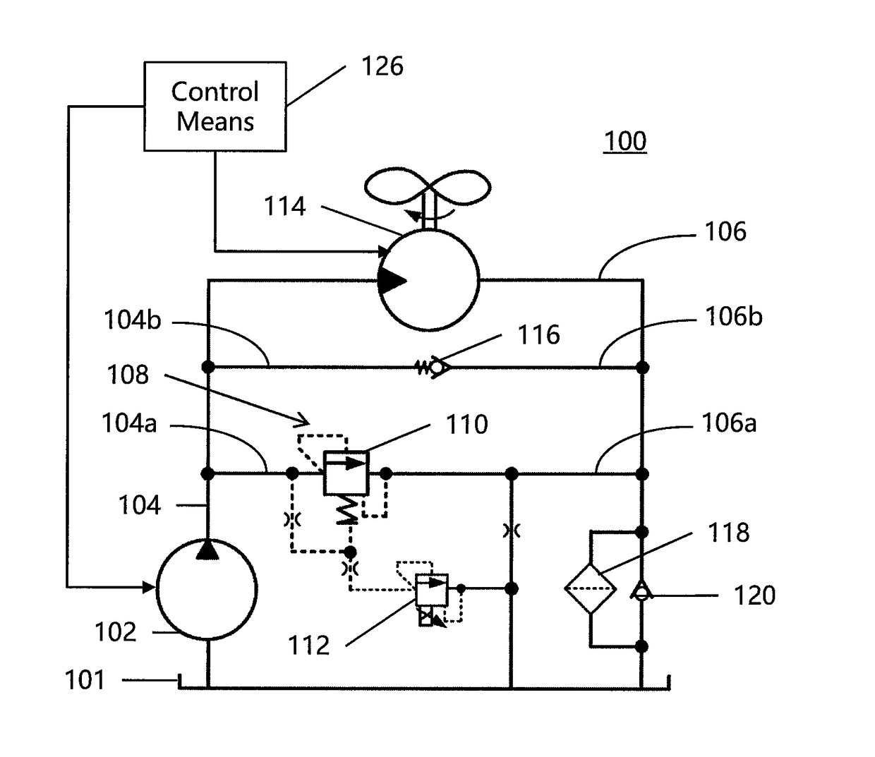
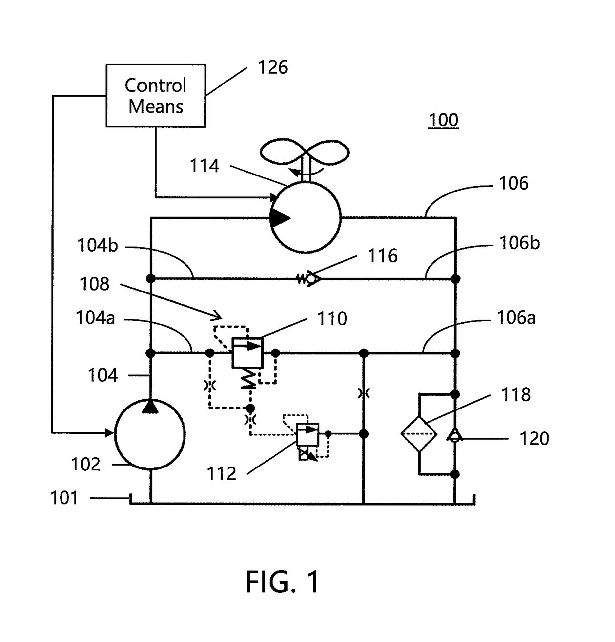
[0055]Referring now to FIG. 1, there is illustrated a typical hydraulic fan drive system 100 for cooling an engine (not shown). The hydraulic fan drive system can be composed of any desired drive system including, but not limited to, one of a gear pump system, an open-circuit piston pump system, a closed-loop hydrostatic system, or a combination thereof. As illustrated in FIG. 1, the system 100 includes a fixed displacement hydraulic pump 102 and a supply tank 101 containing a cooling fluid (e.g., oil). The fixed displacement hydraulic pump 102 is adapted to draw the fluid from tank 101 and direct the fluid to a fan motor 114 via supply line 104. Supply line 104 further includes valve supply line 104a, which provides fluid to pressure controlling valve system 108, and valve supply line 104b, which provides fluid to directional spring-controlled check valve 116. Fan exhaust line 106 and valve exhaust lines 106a, 106b are configured to redirect fluid to tank 101. The exhausted fluid c...


PUM


Abstract

A control system that uses an algorithm to control the fan speed in a cooling system for an engine is disclosed. The algorithm is adapted to maintain a cooling medium at a set temperature instead of an operating temperature range of the cooling medium. The algorithm is also adapted to maintain a cooling medium at a set temperature and to build a cooling safety margin in response to an engine output torque percentage that is below an output torque percentage setpoint.

Description

CROSS REFERENCE TO RELATED APPLICATIONS[0001]This application claims priority to U.S. Provisional Application Nos. 62 / 503,576, filed May 9, 2017, and 62 / 561,831, filed Sep. 22, 2017, the disclosures of which are herein incorporated by reference in their entirety.BACKGROUND[0002]The present disclosure relates to cooling systems, particularly to fan drive systems that include a pump for engine cooling, and more particularly to a control system that uses an algorithm to control fan drive systems and provide for improved cooling thereof.[0003]Cooling systems are widely used in engines for any number of machines, including cars, trucks, heavy machinery, airplanes, etc. However, cooling systems implemented in such machines are known to suffer various drawbacks, including disproportionate use of engine power output, low efficiencies, high emissions, short life, loud noise from fan acceleration, etc.[0004]It would be desirable to provide a novel control system that uses an algorithm to cont...

Claims


Application Information

Patent Timeline
IPC IPC(8): F01P7/04F04D29/58
CPCF01P7/044F01P7/048F04D29/584F04D29/5826F01P2023/08F01P2025/13F01P2025/30F04D27/004F01P2025/62Y02B30/70
Inventor BABBITT, WENLING
Owner APPLIED IND TECH
Why Eureka
Try Eureka