Pressure Pipe Connection Method and Method for Constructing Pressure Pipe with Flange

a pressure pipe and connection method technology, applied in the direction of flanged joints, pipe joints, sleeves/socket joints, etc., can solve the problems of reducing the breaking strength of the pressure pipe itself, limiting the ability of the person to perform the work, etc., to achieve high machining skill, reduce machining man-hours, the effect of performing comparatively easily and accurately

Inactive Publication Date: 2018-11-15
NIPPON KANSEN INDS
View PDF15 Cites 4 Cited by
  • Summary
  • Abstract
  • Description
  • Claims
  • Application Information

AI Technical Summary

Benefits of technology

[0013]According to the present invention, there is an effect that piping work is performed with reducing machining man-hours for the pressure pipes and without requiring high machining skill because a work for cutting a groove, into which the arc members are fitted, for the pressure pipes cut to an even required length can be performed comparatively easily and accurately by utilizing a lathe and, once the cutting work is done, the remaining piping work can be completed by combing parts such as a sleeve, flange and bolts prepared previously.

Problems solved by technology

Such a welding work requires skill, and therefore, the person who can perform the work is limited.
The non-penetrating holes provided on the pressure pipe reduces the breaking strength of the pressure pipe itself.

Method used


Image

  • Pressure Pipe Connection Method and Method for Constructing Pressure Pipe with Flange
  • Pressure Pipe Connection Method and Method for Constructing Pressure Pipe with Flange
  • Pressure Pipe Connection Method and Method for Constructing Pressure Pipe with Flange

Examples


example 1

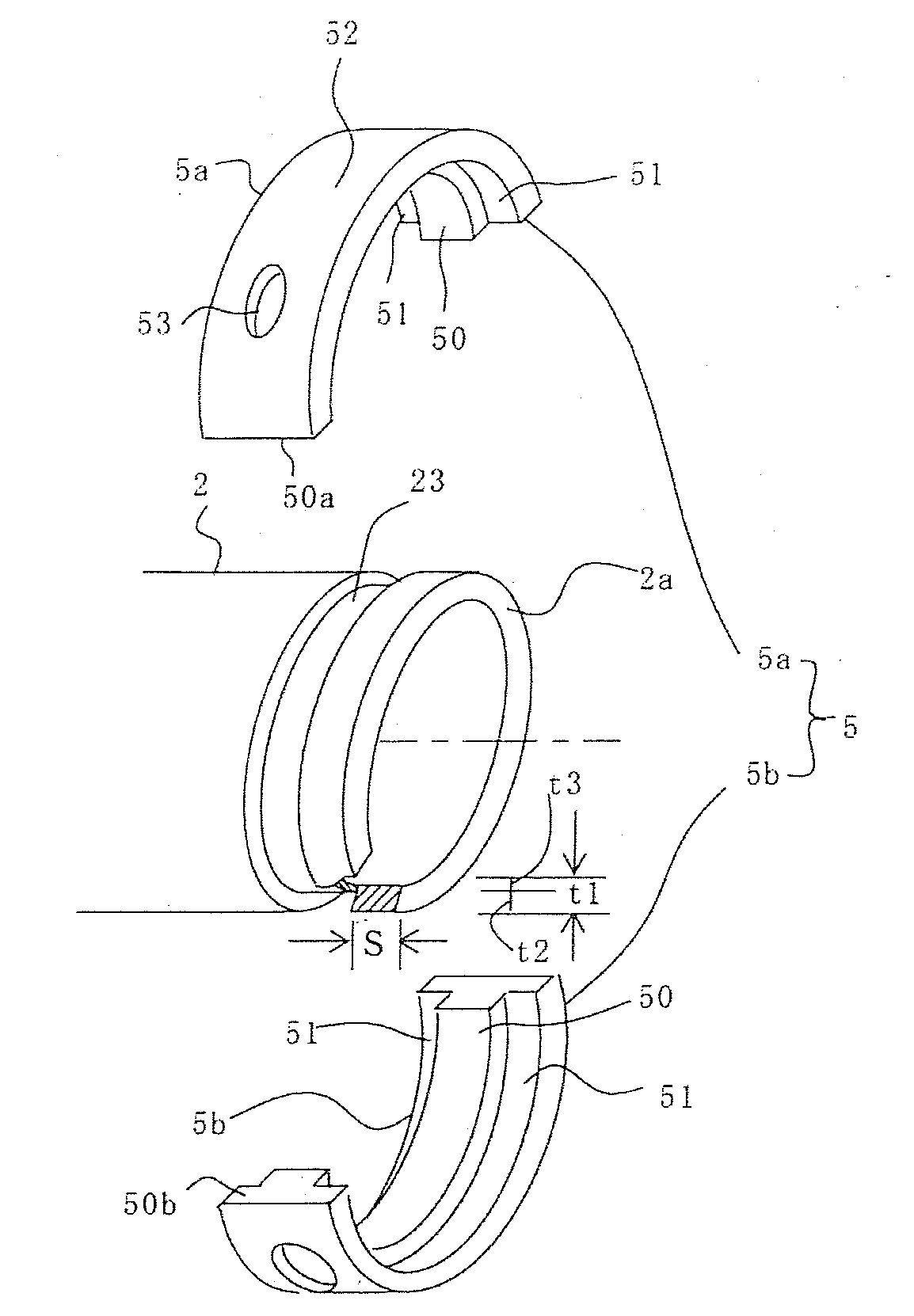
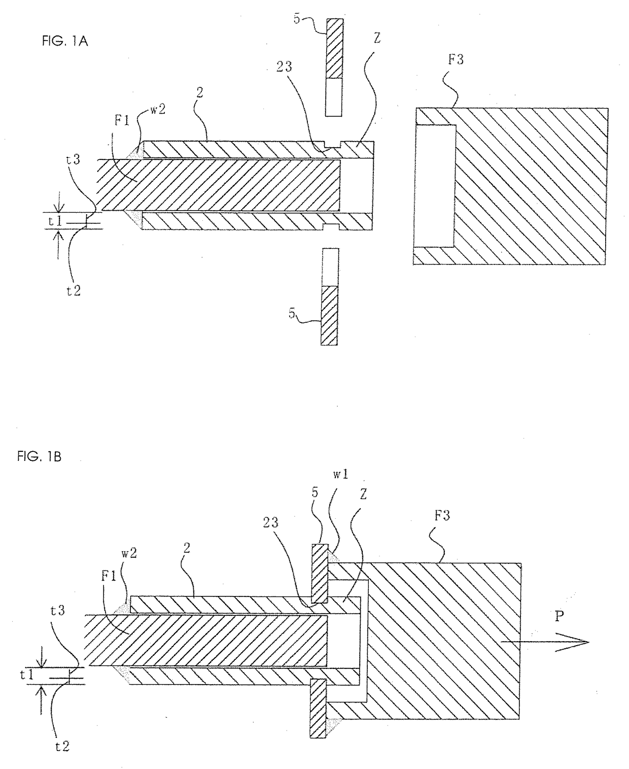
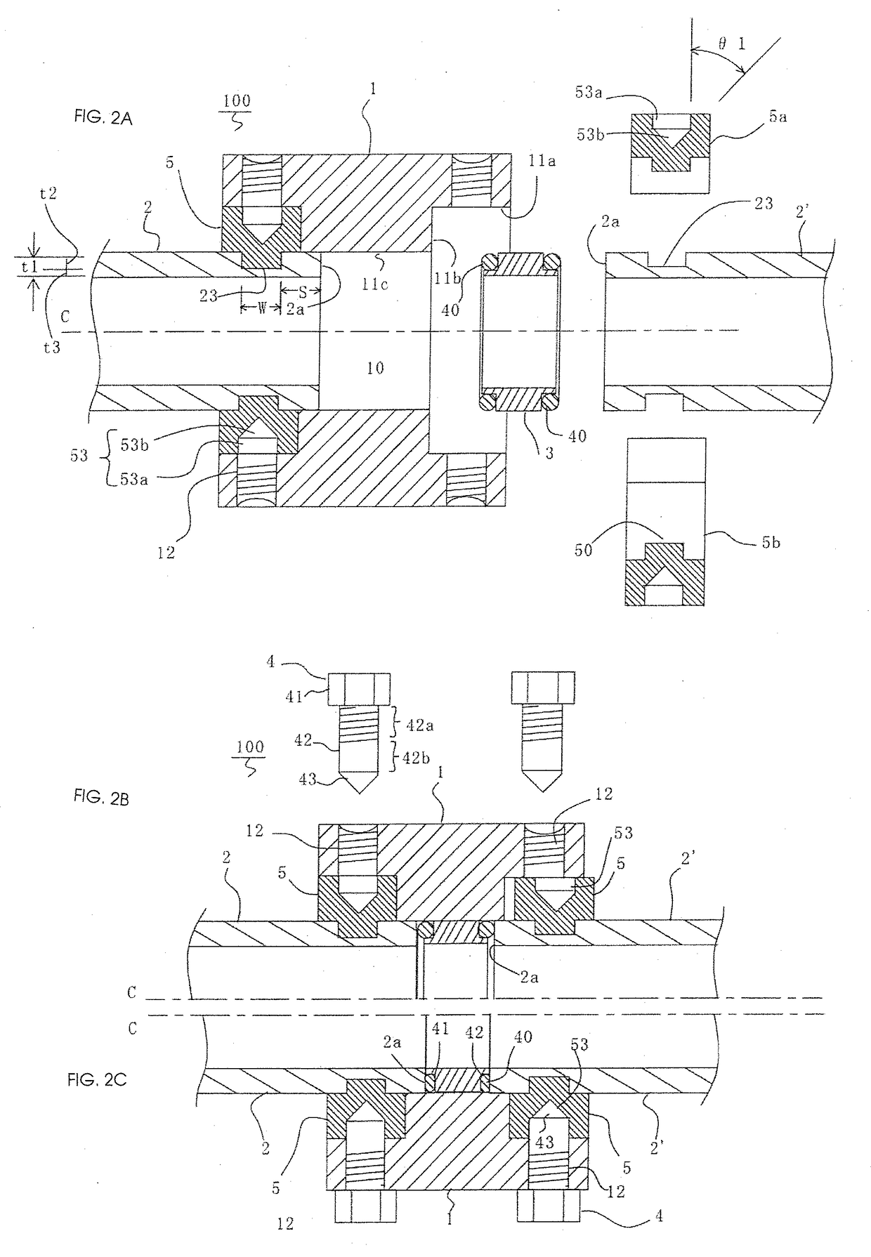
[0031]FIGS. 2A and 2B show a connection structure 100 relating to the first embodiment, which shows an example of a sleeve joint for connecting pressure pipes. The connection structure 100 includes a sleeve 1, pressure pipes 2 and 2′, an insert 3, a plurality of bolts 4 and a ring 5. The sleeve 1, the insert 3, the bolts 4 and the ring 5 are mass produced at a factory in advance. On the other hand, although the pressure pipes 2 and 2′ themselves are standardized mass-produced articles, their lengths are cut and adjusted corresponding to an equipment installed thereto.

[0032]The sleeve 1 is a straight cylinder having a hollow 10 into which the pressure pipes 2 and 2′ are respectively inserted from opposing entrances to each other. Each of the entrances is provided with a step 11b retreating radially outside on the entire circumference of the sleeve. The step 11b radially retreats from the hollow 10 and reaches inner cylindrical surface 11a externally fitting the outer circumference of...

example 2

[0043]Example 2 is shown in FIGS. 5A and 5B. In Example 1, the cross section of the ring 5 has the projecting part 50 which is T-shaped in cross-section, whereas in this example, a ring 55 has a rectangular cross section. The ring 55 includes arc members 55a and 55b that form a circle. The ring 55 has the same non-though holes 53 as the ring 5 has. In comparison with the ring 5, the ring 55 is inferior in terms of strength because the ring 55 has no portion 51 being in contact with the outer circumferential surface of the pressure pipe 2. However, there is an advantage that the production cost is reduced because the portion 51 need not be molded.

example 3

[0044]Although the insert 3 for housing the O-ring 40 is independent of the sleeve 1 in Example 1, the insert 3 in Example 3 depicted in FIGS. 6A, 6B, 6C and 6D is integrated with a sleeve 300. In this case, in order to house the O-ring 40 having as large a diameter as possible, the end part of the pressure pipe 2 is machined into the male taper surface 2b inclined at the taper angle θ2 (FIG. 6C), and female taper surfaces 321 and 322 for receiving the male taper surface 2b are provided on the sleeve 300 (FIG. 6D). A hollow 310 of the sleeve 300 includes a projecting portion 320 projecting to a position of the radius equal to the inner diameter of the pressure pipe 2. The projecting portion 320 has the female taper surfaces 321 and 322 toward the exits of the hollow 310 of the sleeve 300, and O-ring grooves 323 and 324 for housing the O-rings 40 are provided in the middle of the female taper surfaces 321 and 322, respectively. The female taper surfaces 321 and 322 are in surface con...


PUM


Abstract

Provided is a pressure pipe connection structure that reduces man-hours for machining one or more pressure pipes and does not require high machining precision. Multiple arc members form a ring shape that makes a circle by matching the end faces thereof to each other. Non-penetrating holes may be provided on the outer circumference of the arc members. The ring formed by the multiple arc members has an inner diameter that is smaller than the outer diameter and larger than the inner diameter of a pressure pipe. A cylindrical sleeve has an inner cylindrical surface inside which the entire outer circumferences of arc members are fitted into a hollow internal space, into which respective one or more pressure pipes are inserted from one or more opposing entrances; and multiple through holes, which penetrate from the outside and are provided with female thread ridges. The one or more pressure pipes are cut to a certain length that is suited to the placement site and a groove is grooves cut in the corresponding pressure pipe. The arc members are fitted into the groove, and the arc members are positioned on an inner cylindrical surface by inserting the one or more pressure pipes into a sleeve, the respective through holes and non-penetrating holes are made to communicate with each other, and the one or more pressure pipes are fixed using bolts.

Description

TECHNICAL FIELD[0001]The present invention relates to a pressure pipe connection method and a method for constructing pressure pipes with a flange that enable connecting pressure pipes cut to a certain length that is suited to a placement site without requiring welding.BACKGROUND ART[0002]A carbon steel pipe (STPG) is used as a steel pipe for pressure piping. The carbon steel pipe has a minimum yield load and a breaking strength determined by the Japanese Industrial Standards (JIS). On the other hand, a coupling joint for connecting pressure pipes requires the yield load and the breaking strength exceeding those of the pressure pipes. Specifically, a tension test sets a joint strength to such strength that the connected pressure pipe base material should be cut. In addition, in the welding connection, the pressure pipe is required to extend a leg length on the entire circumference in order to keep such weld strength that the pressure pipe base material should be cut in the same way....

Claims


Application Information

Patent Timeline
Patent Type & Authority Applications(United States)
IPC IPC(8): F16L21/08F16L23/024
CPCF16L21/08F16L23/024F16L23/0283F16L23/032F16L25/065
Inventor KOBAYASHI, MASATO
Owner NIPPON KANSEN INDS
Why Eureka
Try Eureka